12vdc To 120vac Inverter Circuit Diagram Wiring Digital And Schematic

12vdc To 120vac Inverter Circuit Diagram в Wiring Digital And Schematic A schematic diagram is a compilation of drawings, symbols, and letters that represent an electrical circuit and its components. drawing a schematic diagram is important as it helps to visualize the components and wiring of a 120v inverter before beginning construction. the schematic diagram starts with the input source, which is often a 12 volt. Enter the 12vdc to 120vac inverter circuit diagram. the 12vdc to 120vac inverter circuit diagram is an easy to use schematic for converting direct current (dc) electricity from a 12v source into alternating current (ac) electricity at 120 volts. this type of inverter is not just for travelers – it can also be helpful for creating a backup.

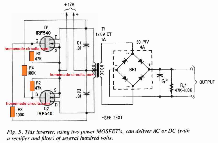
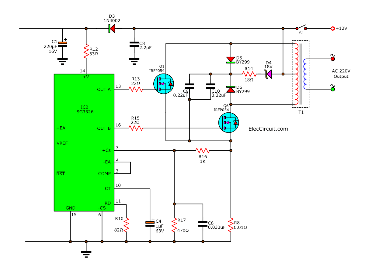
12vdc To 120vac Inverter Circuit Diagram Wiring Digital And Schematic A shunt resistor is used in the circuit for current sensing and overcurrent protection. instead of using those bulky high power resistors, you can use a solid wire of copper as a makeshift low profile shunt resistor. i stripped a guage 12 solid wire, cut it to 60mm, bent it then soldered it to the board. Here is a simple 12 volts dc to ac inverter circuit. this 120v ac power source is built with a simple 120v:24v or 110v:24v center tapped control transformer and four additional component. this circuit outputs a clean 200 v pk pk square wave at 60 hz and can supply up to 20w. the circuit is self starting and free running. Basic inverter. the following diagram is the basic design diagram of inverter circuit. the circuit will convert 12v dc to 120v ac. this basic inverter circuit can handle up to 1000watts supply depends the t1, t2 and transformer used. please see the note. This is a basic and very simple low power inverter to convert 12v dc to 120v ac. how much power this simple inverter can handle the load depends the transformer current value and transistors you use for q1 and q2. inverter 12v dc to 120v ac component list: c1, c2 : 68 uf, 25 v tantalum capacitor. r1, r2 : 10 ohm, 5 watt resistor.

12vdc To 120vac Inverter Circuit Diagram Wiring Digital And Schematic Basic inverter. the following diagram is the basic design diagram of inverter circuit. the circuit will convert 12v dc to 120v ac. this basic inverter circuit can handle up to 1000watts supply depends the t1, t2 and transformer used. please see the note. This is a basic and very simple low power inverter to convert 12v dc to 120v ac. how much power this simple inverter can handle the load depends the transformer current value and transistors you use for q1 and q2. inverter 12v dc to 120v ac component list: c1, c2 : 68 uf, 25 v tantalum capacitor. r1, r2 : 10 ohm, 5 watt resistor. A 12vdc to 120vac inverter circuit diagram is a schematic diagram that shows the electrical components and their connections. it explains how power is transformed from a 12 volt battery to a 120 volt ac outlet. it also explains the circuitry necessary to convert the current from dc to ac. Introduction to power inverter design 12 24 vdc input 120 or 240 vac 50 60 hz output blog energy element14 community. 25w low power inverter electronic schematic diagram. 12v to 220v 100w transistor inverter. 12v to 230v inverter circuit using pwm ic sg3525 100 watt diagram circuits gallery. 12v to 120v dc converter circuit.

Comments are closed.