4l60e Valve Body Diagram Transmission Cooler Guide

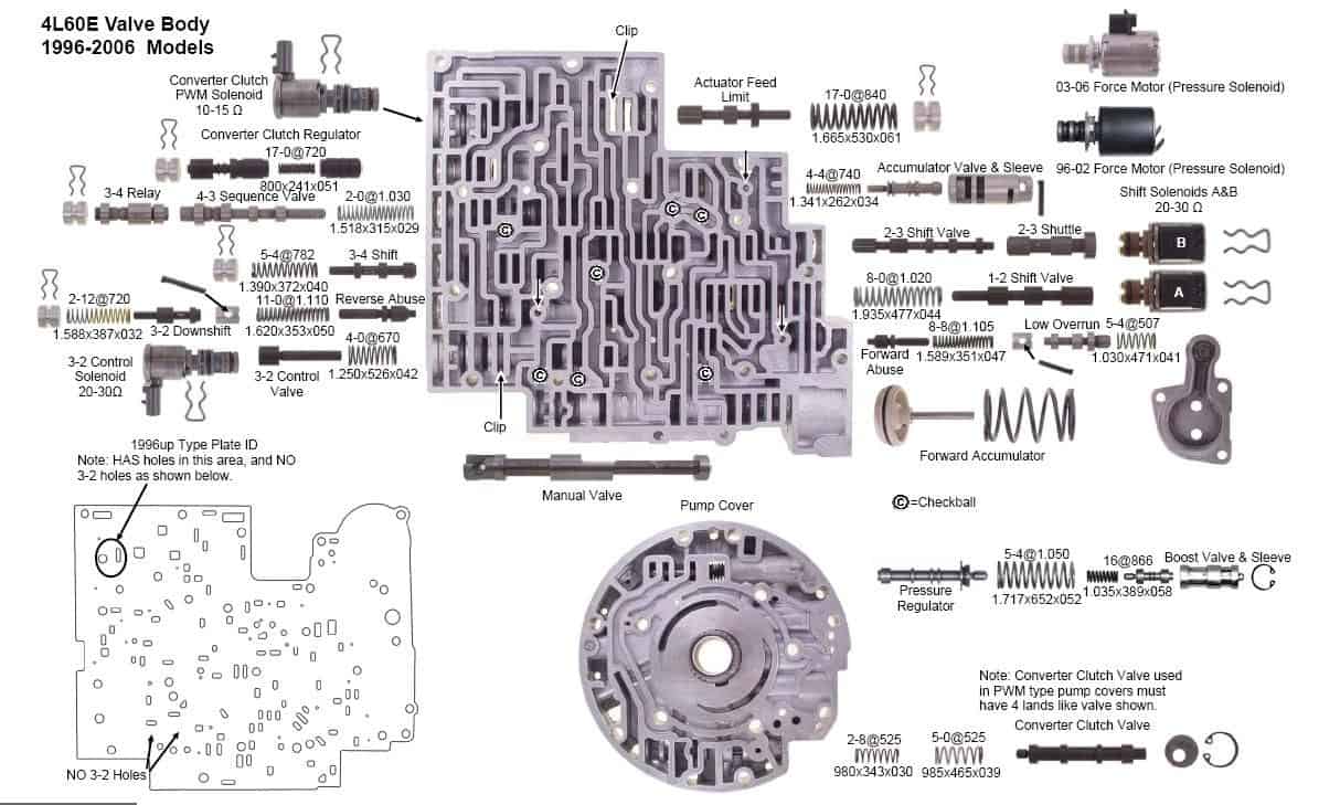
4l60e Valve Body Diagram Transmission Cooler Guide 4l60e valve body diagram. powered by wordpress and hitmag. view all internal parts with this helpful 4l60e valve body diagram. get more information about the 4l60e transmission valve body assembly. When you are finished with the installation, mounting, and plumbing, your transmission cooling diagram will look like this: transmission >feed line >radiator(stock cooler) >aftermarket tranny cooler >return line >transmission it is ideal to splice the transmission cooler into the return line, so that way the coolant flows through the stock in.

4l60e Valve Body Diagram Number of valve body solenoids: 5: epc solenoid: late: 3 2 control solenoid: on off (plastic, white) 20 31 Ω: tcc solenoid: pwm (plastic, gray) 10 15 Ω: manual valve: vented: casting: bottom: angled by epc and accumulator valve bottom: tcc annular exhaust port top: tcc annular exhaust port bottom: 3 2 port cast shut bottom: vent at manual. What causes a 4l60e transmission to slip. torque converter lockup problems. common problems. diagnostic trouble codes (dtc) wiring & diagrams. internal parts diagram. wire harness diagram. neutral safety switch diagram. 1 2 accumulator diagram. Shift solenoid guide; transmission cooler line flow; 4l60e valve body diagram showing internal parts and locations within the valve body. learn more. 1993 – 1994 4l60e valve body identification. number of valve body solenoids: 4. epc solenoid: early. 3 2 control solenoid: pwm (metal, white) 10 15 Ω. tcc solenoid: none. manual valve: non vented. casting: bottom – open port over 3 2 valve, bottom – no vent at manual valve. part number: gm046.

Gm 4l60e Transmission Cooler Line Diagram Shift solenoid guide; transmission cooler line flow; 4l60e valve body diagram showing internal parts and locations within the valve body. learn more. 1993 – 1994 4l60e valve body identification. number of valve body solenoids: 4. epc solenoid: early. 3 2 control solenoid: pwm (metal, white) 10 15 Ω. tcc solenoid: none. manual valve: non vented. casting: bottom – open port over 3 2 valve, bottom – no vent at manual valve. part number: gm046. 4l60e rebuild manual pdf. download a free 186 page 4l60e rebuild manual pdf and procedures guide. this covers all you need to know about the ins and outs of rebuilding a 4l60e transmission. read more. Gm 4l60 e, 4l65 e, 4l70 e valve body layout.

4l60e Transmission Valve Body Diagram 4l60e rebuild manual pdf. download a free 186 page 4l60e rebuild manual pdf and procedures guide. this covers all you need to know about the ins and outs of rebuilding a 4l60e transmission. read more. Gm 4l60 e, 4l65 e, 4l70 e valve body layout.

4l60e Valve Body Diagram Transmission Cooler Guide

Comments are closed.