5 Pin Cdi Wiring Diagram Color Code

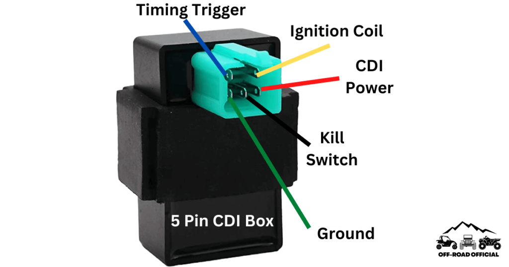
5 Pin Cdi Wiring Diagram Pictured And Explained Off Road Official On a 5 pin cdi system, you will find 5 different colored wires coming out of the cdi unit: green – connects to pickup coil signal input. white – connects to ac input from stator. red – main power source ( 12v from battery) black – main ground ( connection to battery) blue – output to ignition coil. The 5 pin cdi box. the 5 pin cdi comes in the form of a black box, fitted with a male connector at the top. inside of this male connector, there are five different pins that connect to the various parts of the ignition system to provide power to the machine. these five pins connect the timing trigger pulse generator, ignition coil, ignition.

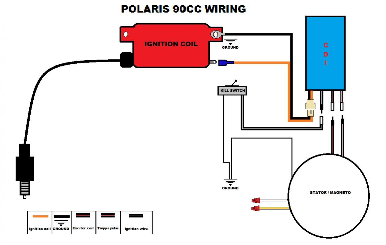
5 Pin Cdi Wiring Diagram Pictured And Explained Off Road Official Wiring a cdi involves connecting various wires and components, such as the stator, pickup coil, and ignition coil, in the correct sequence and configuration. this diagram shows you exactly how to wire a 5 pin cdi. each wire is labeled and color coded, making it easy to identify and connect the correct wires. The 5 pins on the cdi connector supply power, ground, and signals to control this process. here is a quick overview of each pin’s function: pin 1 – ground. pin 2 – 12vdc from battery via ignition switch and fuses. pin 3 – trigger signal from ac generator stator. pin 4 – switched 12vdc to ignition coil. Try edrawmax and make 5 pin cdi wiring diagram easily bit.ly 3bjwffz explore wiring diagrams, and free use and edit 5000 diagram examples here http. A 5 pin dc cdi wiring diagram maps out electrical circuits by assigning each wire a color code, pin number, and symbol. by following the flow of electricity, technicians can identify which components are receiving power, and which aren’t. when viewing a 5 pin dc cdi wiring diagram, you will generally see five columns labeled: pin number.

5 Pin Cdi Wiring Diagram Color Code Try edrawmax and make 5 pin cdi wiring diagram easily bit.ly 3bjwffz explore wiring diagrams, and free use and edit 5000 diagram examples here http. A 5 pin dc cdi wiring diagram maps out electrical circuits by assigning each wire a color code, pin number, and symbol. by following the flow of electricity, technicians can identify which components are receiving power, and which aren’t. when viewing a 5 pin dc cdi wiring diagram, you will generally see five columns labeled: pin number. Overall, identifying the wires in a 5 wire cdi is an essential step in the installation process. taking the time to understand the functions and colors of each wire will help you connect everything correctly and ensure the proper functioning of your cdi unit. the black wire. the black wire is a vital component in the 5 wire cdi wiring diagram. The most common wire colors found on a 5 pin cdi box are black, red, white, blue, and green. the black wire is usually connected to the vehicle’s ground or negative terminal. it provides the ground connection for the cdi box and completes the electrical circuit.

Comments are closed.