5 Pin Dc Cdi Wiring Diagram Enhobby

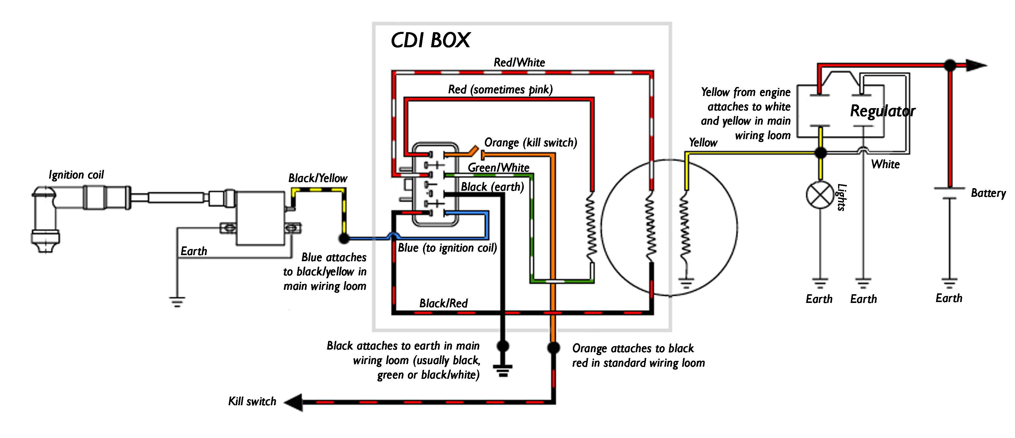
5 Pin Dc Cdi Wiring Diagram Enhobby The 5 pin cdi box. the 5 pin cdi comes in the form of a black box, fitted with a male connector at the top. inside of this male connector, there are five different pins that connect to the various parts of the ignition system to provide power to the machine. these five pins connect the timing trigger pulse generator, ignition coil, ignition. On a 5 pin cdi system, you will find 5 different colored wires coming out of the cdi unit: green – connects to pickup coil signal input. white – connects to ac input from stator. red – main power source ( 12v from battery) black – main ground ( connection to battery) blue – output to ignition coil.

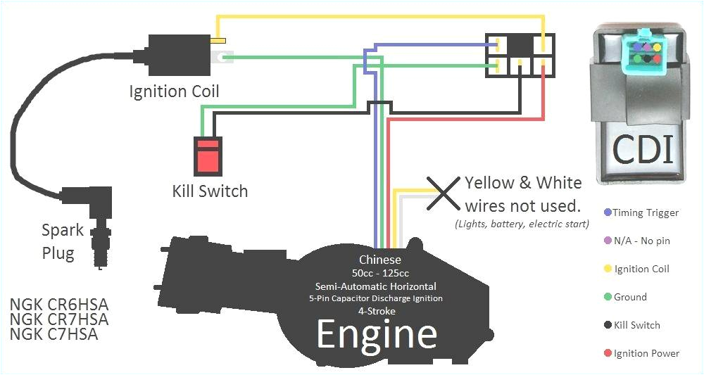
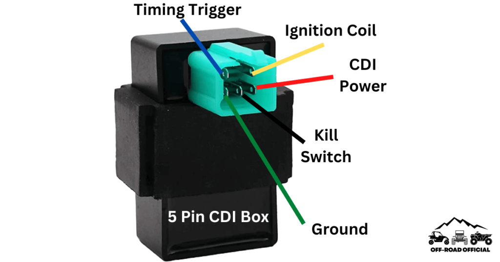
5 Pin Cdi Wiring Diagram Pictured And Explained Off Road Official Pin 1: power output – this pin is connected to the ignition coil and provides the high voltage spark. pin 2: ground – this pin is connected to the engine’s ground or chassis. pin 3: charging coil – this pin is connected to the engine’s charging coil, which generates the electrical power for the cdi unit. An understanding of the diagram is essential for correctly installing or troubleshooting the system. this article will provide a detailed overview of a 5 pin dc cdi wiring diagram. components. the diagram shows the components of the 5 pin dc cdi system, including the spark plug, ignition coil, capacitor, and ignition switch. The five pins are located inside of the connector and are responsible for providing power to the engine by linking the various parts of the ignition system together. these five pins connect the following components: timing trigger (or pulse generator) ignition coil. cdi ignition power. kill switch (or key switch). The most common wire colors found on a 5 pin cdi box are black, red, white, blue, and green. the black wire is usually connected to the vehicle’s ground or negative terminal. it provides the ground connection for the cdi box and completes the electrical circuit.

5 Pin Dc Cdi Wiring Diagram Enhobby The five pins are located inside of the connector and are responsible for providing power to the engine by linking the various parts of the ignition system together. these five pins connect the following components: timing trigger (or pulse generator) ignition coil. cdi ignition power. kill switch (or key switch). The most common wire colors found on a 5 pin cdi box are black, red, white, blue, and green. the black wire is usually connected to the vehicle’s ground or negative terminal. it provides the ground connection for the cdi box and completes the electrical circuit. The 5 pins on the cdi connector supply power, ground, and signals to control this process. here is a quick overview of each pin’s function: pin 1 – ground. pin 2 – 12vdc from battery via ignition switch and fuses. pin 3 – trigger signal from ac generator stator. pin 4 – switched 12vdc to ignition coil. This article will provide a detailed guide on how to interpret and connect the wiring diagram for a dc cdi ignition system. first and foremost, it’s crucial to identify the different components of a typical dc cdi ignition system. these components include the stator, magnet, ignition coil, cdi unit, kill switch, spark plug, and battery.

5 Pin Cdi Wiring Diagram Pictured And Explained Off Road Official The 5 pins on the cdi connector supply power, ground, and signals to control this process. here is a quick overview of each pin’s function: pin 1 – ground. pin 2 – 12vdc from battery via ignition switch and fuses. pin 3 – trigger signal from ac generator stator. pin 4 – switched 12vdc to ignition coil. This article will provide a detailed guide on how to interpret and connect the wiring diagram for a dc cdi ignition system. first and foremost, it’s crucial to identify the different components of a typical dc cdi ignition system. these components include the stator, magnet, ignition coil, cdi unit, kill switch, spark plug, and battery.

5 Pin Dc Cdi Wiring Diagram Enhobby

Comments are closed.