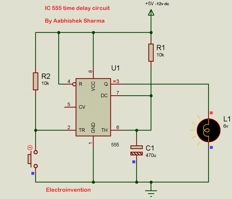
555 Timer Circuit Instant On Delayed Off Self Start Self Initialization With Just 3 Components

555 Timer Circuit Instant On Delayed Off Self Start This timer circuit is activated by power on. here are two of the simplest circuits you can build with a 555 timer and just one or 2 resistors and one or 2 c. Step 1: 555 timer ic in monostable mode. lets start by putting all the components together and lets understand how the circuit works. in the first example, i am going to show you guys the "on off timer circuit" with a fixed timing resistor and capacitor. the heart of this circuit is the 555 timer ic.

555 Timer Delay Off Circuit Diagram Eeweb I created the following circuit that seems to be able to accomplish that task with just one 555 and no external triggers. explanation of my circuit: the left side attempts to simulate a delayed trigger pulse. r1 c1 is slowly decreasing the voltage from high to low and manipulates the length of time when output will be on low (~15 seconds). A 555 timer can give out only 100 to 200 ma in total. check your chip’s datasheet for the exact value. this pin resets the whole circuit. it’s an “inverted” pin, which means it resets when the pin goes low. this means the pin must be high normally so that the chip isn’t in a “reset” state. The 555 timer delay before turn off circuit we will build is shown below. the breadboard schematic of the above circuit is shown below. to connect power to the 555 timer chip, we connect about 5 15v to v cc, pin 8, and we connect pin 1 to ground. we connect a 47kΩ resistor to the positive voltage supply and then to pin 2. 555 circuits part 1. a collection of 555 circuits using the 555 timer as an astable oscillator with different duty cycles. we have seen in the last few tutorials that the 555 timer can be configured with externally connected components as multivibrators, oscillators and timers, with timing intervals ranging from a few microseconds to many hours.

Ic 555 Delay Timer Circuit Easy Timer Circuit On Off De The 555 timer delay before turn off circuit we will build is shown below. the breadboard schematic of the above circuit is shown below. to connect power to the 555 timer chip, we connect about 5 15v to v cc, pin 8, and we connect pin 1 to ground. we connect a 47kΩ resistor to the positive voltage supply and then to pin 2. 555 circuits part 1. a collection of 555 circuits using the 555 timer as an astable oscillator with different duty cycles. we have seen in the last few tutorials that the 555 timer can be configured with externally connected components as multivibrators, oscillators and timers, with timing intervals ranging from a few microseconds to many hours. 555 timer (en555) the 555 timer is an integrated circuit, it is extremely versatile and can be used to build lots of different circuits. the en555 is usually used to generate continuous series of pulses. these series of pulses allow you to continuously blink an led, for example. the 555 timer can operate in three different modes:. Here’s the internal schematics of 555 timer which consists of 25 transistors, 2 diodes and 15 resistors. represented with a block diagram it consists of 2 comparators, a flip flop, a voltage divider, a discharge transistor and an output stage. the voltage divider consists of three identical 5k resistors which create two reference voltages at.

555 Timer Switch Circuit Diagram 555 timer (en555) the 555 timer is an integrated circuit, it is extremely versatile and can be used to build lots of different circuits. the en555 is usually used to generate continuous series of pulses. these series of pulses allow you to continuously blink an led, for example. the 555 timer can operate in three different modes:. Here’s the internal schematics of 555 timer which consists of 25 transistors, 2 diodes and 15 resistors. represented with a block diagram it consists of 2 comparators, a flip flop, a voltage divider, a discharge transistor and an output stage. the voltage divider consists of three identical 5k resistors which create two reference voltages at.

Comments are closed.