555 Timer Ic Block Diagram Working Pin Out Configuration Data Sh
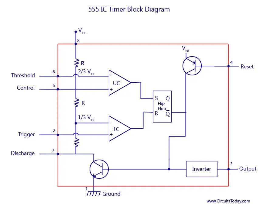
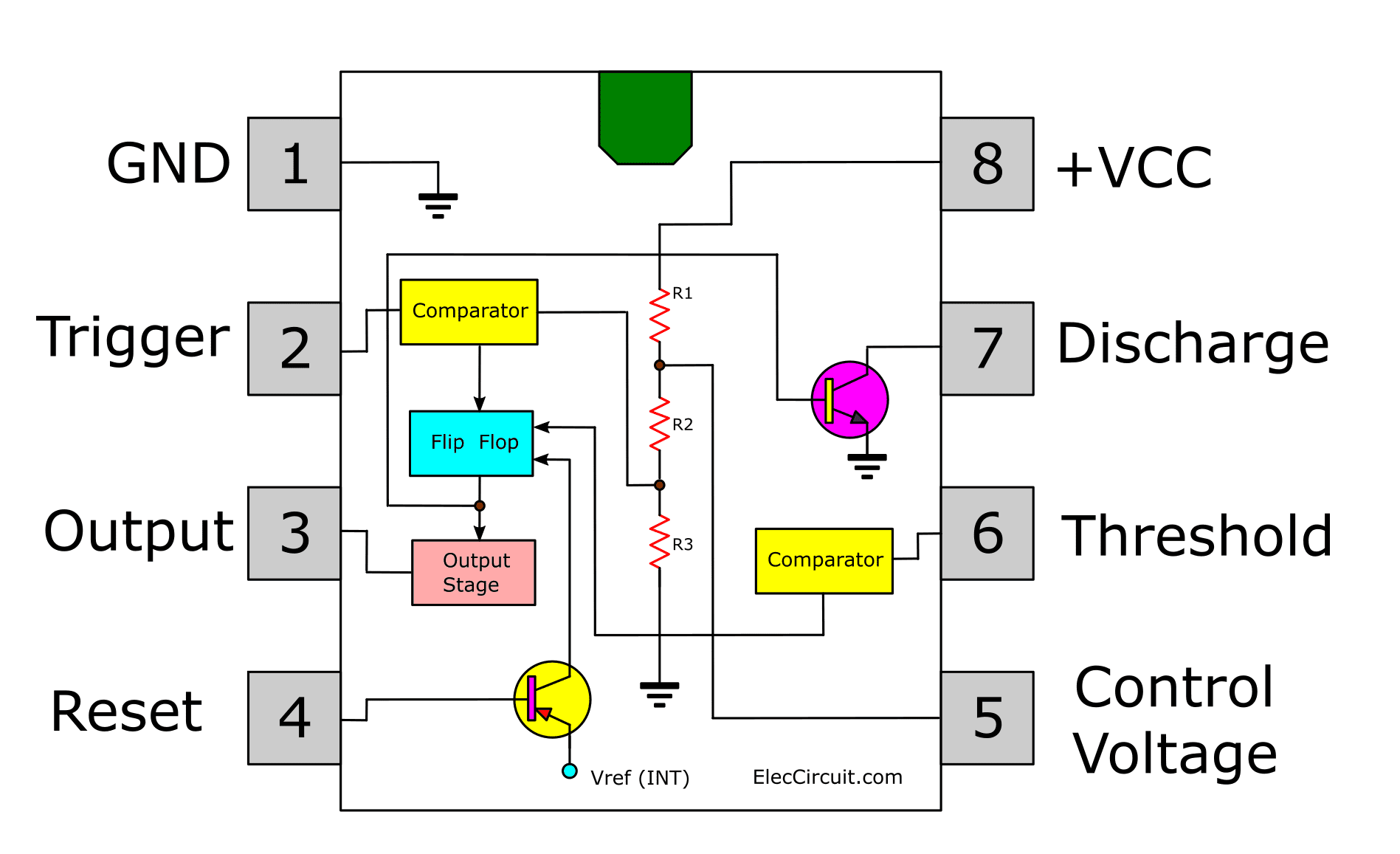
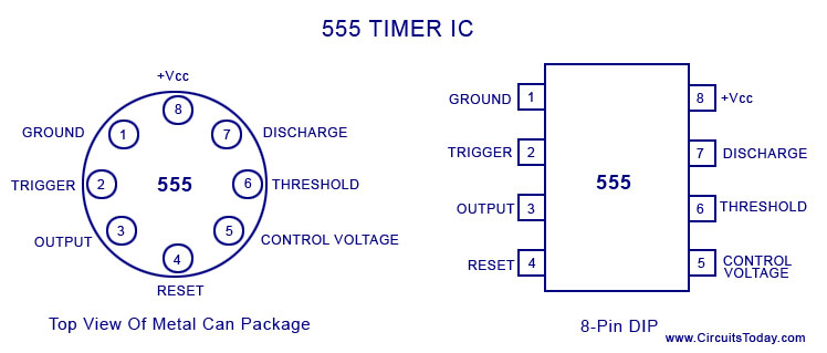
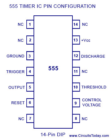
555 Timer Ic Block Diagram Working Pin Out Config 555 timer ic pin configuration. the 555 timer ic is available as an 8 pin metal can, an 8 pin mini dip (dual in package) or a 14 pin dip. the pin configuration is shown in the figures. this ic consists of 23 transistors, 2 diodes and 16 resistors. the use of each pin in the ic is explained below. Here’s the internal schematics of 555 timer which consists of 25 transistors, 2 diodes and 15 resistors. represented with a block diagram it consists of 2 comparators, a flip flop, a voltage divider, a discharge transistor and an output stage. the voltage divider consists of three identical 5k resistors which create two reference voltages at.
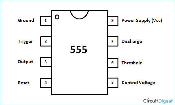
555 Timer Ic Internal Structure Working Pin Diagram And Descript The document provides a complete basic guide to the 555 timer ic, covering: 1. the 555 timer ic was introduced in 1970 and gives accurate time delays or oscillations for applications like waveform generation and temperature control. 2. it has an 8 pin configuration and works in monostable or astable modes, with features like wide voltage range and high current output. 3. internally it contains. 555 timer operating modes. there are three operating modes of the 555 timers: astable mode: in this mode output at pin 3 continuously fluctuates between state ‘high’ and ‘low’. this mode is used in applications where we need 555 timer as clock source. monostable mode: in this mode output turns ‘high’ for particular period of time. Features of 555 timer ic. there are two types of 555 timer based on its nomenclature – ne 555 timer and se 555 timer. while ne 555 timer can be used in the temperature range from 0 to 70°c, the se 555 timer can be used in the temperature range from 55°c to 125°c and has a temperature stability of 0.005% per 0c. Thus by varying r or c, the output pulse width can be varied. this is the working principle of timer ic 555 timer circuit. ic 555 pin diagram: the fig. 2.100 (a) and (b) show the ic 555 pin diagram and the ic 555 timer block diagram. this is 8 pin ic timer.
Ic 555 Timer Circuit Diagram Features of 555 timer ic. there are two types of 555 timer based on its nomenclature – ne 555 timer and se 555 timer. while ne 555 timer can be used in the temperature range from 0 to 70°c, the se 555 timer can be used in the temperature range from 55°c to 125°c and has a temperature stability of 0.005% per 0c. Thus by varying r or c, the output pulse width can be varied. this is the working principle of timer ic 555 timer circuit. ic 555 pin diagram: the fig. 2.100 (a) and (b) show the ic 555 pin diagram and the ic 555 timer block diagram. this is 8 pin ic timer. 3 description. the lm555 is a highly stable device for generating accurate time delays or oscillation. additional terminals are provided for triggering or resetting if desired. in the time delay mode of operation, the time is precisely controlled by one external resistor and capacitor. The se 555 timer ic works between the temperature range of – 55°c to 125°c in se and the ic ne 555 is used for where the temperature ranges from 0° to 70°c. it has a wide range of usages in the electronic field as a timer, delay, pulse generation, oscillator, etc. you can check the datasheet of ne555 ic if you want to learn more about it.
555 Timer Ic Block Diagram Working Pin Out Config 3 description. the lm555 is a highly stable device for generating accurate time delays or oscillation. additional terminals are provided for triggering or resetting if desired. in the time delay mode of operation, the time is precisely controlled by one external resistor and capacitor. The se 555 timer ic works between the temperature range of – 55°c to 125°c in se and the ic ne 555 is used for where the temperature ranges from 0° to 70°c. it has a wide range of usages in the electronic field as a timer, delay, pulse generation, oscillator, etc. you can check the datasheet of ne555 ic if you want to learn more about it.
555 Timer Ic Block Diagram Working Pin Out Config

Comments are closed.