555 Timer Ic Working Principle Block Diagram Circuit Schematics

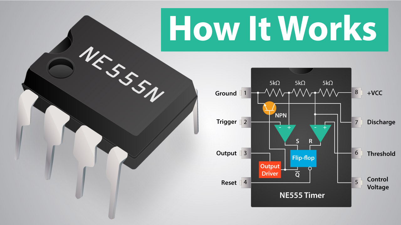
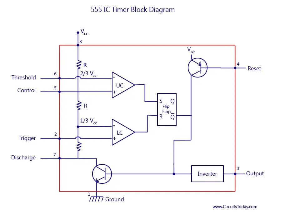
Simple Integrated Circuit Diagram Wiring Diagram And Schematics Here’s the internal schematics of 555 timer which consists of 25 transistors, 2 diodes and 15 resistors. represented with a block diagram it consists of 2 comparators, a flip flop, a voltage divider, a discharge transistor and an output stage. the voltage divider consists of three identical 5k resistors which create two reference voltages at. Basics of 555 timer. 4. block diagram. 5. working principle. 6. download data sheet. if you still need a detailed understanding of the 555 timer ic, we have reviewed 3 books in our online store. these books covers all the aspects of the 555 timer ic, along with its applications.

555 Timer Ic Working Principle Block Diagram Circuit 555 timer is a digital monolithic integrated circuit (ic) which may be used as a clock generator. in other words, 555 timer is a circuit which may be connected as a stable or monostable multivibrator. in more simple words, 555 timer is a monolithic timing circuit, which can produce accurate timing pulses with 50% or 100% duty cycle. It can be found in many electronic devices from electric drills to clocks, radios, and alarm systems. in this article, we'll explore the working principle, block diagram, circuit schematics, and applications of the 555 timer ic. at its core, the 555 timer is a precision timer designed to generate accurate timing signals. A 555 timer can give out only 100 to 200 ma in total. check your chip’s datasheet for the exact value. this pin resets the whole circuit. it’s an “inverted” pin, which means it resets when the pin goes low. this means the pin must be high normally so that the chip isn’t in a “reset” state. A monostable 555 timer is required to produce a time delay within a circuit. if a 10uf timing capacitor is used, calculate the value of the resistor required to produce a minimum output time delay of 500ms. 500ms is the same as saying 0.5s so by rearranging the formula above, we get the calculated value for the resistor, r as:.

555 Timer Ic Block Diagram Working Pin Out Configuration Data Sh A 555 timer can give out only 100 to 200 ma in total. check your chip’s datasheet for the exact value. this pin resets the whole circuit. it’s an “inverted” pin, which means it resets when the pin goes low. this means the pin must be high normally so that the chip isn’t in a “reset” state. A monostable 555 timer is required to produce a time delay within a circuit. if a 10uf timing capacitor is used, calculate the value of the resistor required to produce a minimum output time delay of 500ms. 500ms is the same as saying 0.5s so by rearranging the formula above, we get the calculated value for the resistor, r as:. In short, the 555 timer chip works by detecting threshold voltage levels. pin 2 detects a voltage below 1 3 of the supply voltage to turn the ic on. and, pin 6 detects a voltage above 2 3 of the supply voltage to turn the ic off. i’m a student with a slow brain, learning with illustration causes me more understanding. The 555 timer ic was first introduced around 1971 by the signetics corporation as the se555 ne555 and was called "the ic time machine" and was also the very first and only commercial timer ic available. it provided circuit designers with a relatively cheap, stable, and user friendly integrated circuit for both monostable and astable applications.

Comments are closed.