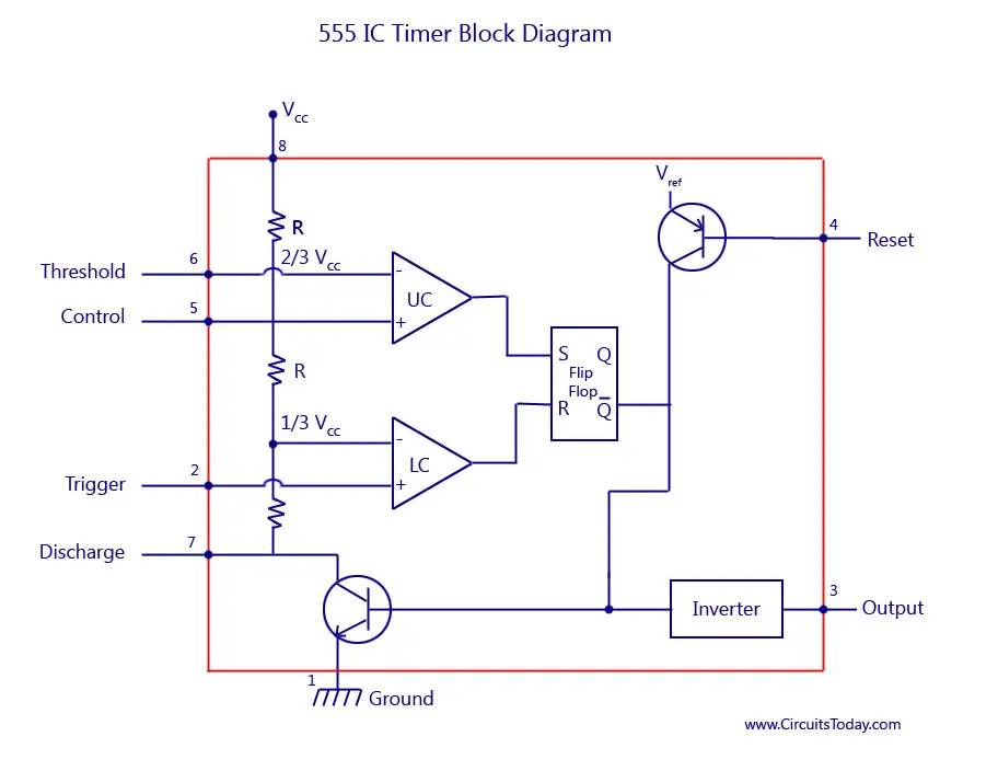
555 Timer Led Flasher Block Diagram Of Ic 555 Timer By Mic

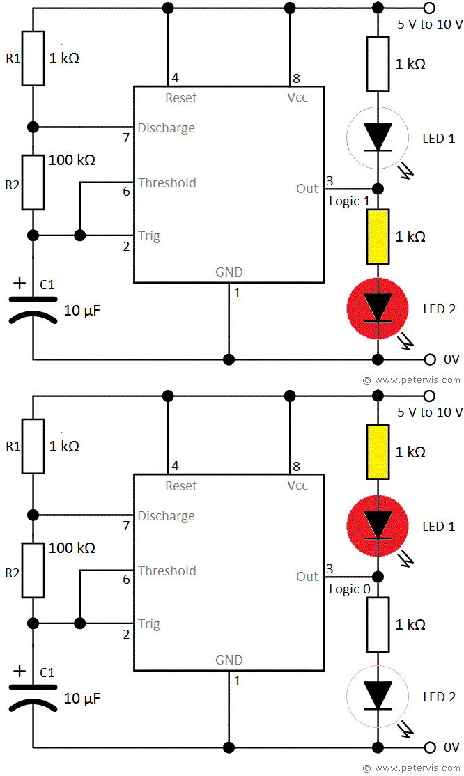
Led Flasher Circuit Diagram With 555 Step 1: building the circuit. to build the circuit, follow these steps: insert the 555 timer ic into the breadboard. connect a 1kΩ resistor between pins 7 of ic and 5v supply ve terminal. connect a 10kΩ potentiometer wiper (middle pin) to pin 7 of the ic. connect the other two terminals of the potentiometer with pin 2 of the ic and 5v ve. The schematic diagram of the led flasher circuit we will build is shown below: this circuit will flash the led on and off, on and off. the rate that the led flashes is determined by the resistors r1 and r2 and the electrolytic capacitor c1. again, the output of a 555 timer are square waves.

555 Timer Led Flasher Block Diagram Of Ic 555 Tim Working explanation. this circuit uses the 555 timers in an astable mode which generates a continuous output in the form of a square wave via pin 3. the rate at which led flashes depends upon the value of the resistor and capacitor used in the circuit. to increase the duty cycle, we will have to use a resistor and capacitors of higher values. Below is the circuit diagram of adjustable dual led flasher that uses a potentiometer to modify the blinking speed: notice how we connected an extra led to the output pin of 555 timer ic. this arrangement allows only 1 led to stay on at any given time, which causes this circuit to function as an alternating led flasher. Step 1: circuit diagram. the circuit is very simple. by connecting pin 2 and 6 of the 555 timer ic, we put the ic in astable mode. in astable mode, the 555 timer ic acts as an oscillator (re triggering itself) generating square waves [pwm signals] from the output pin no. 3. by changing the values of r1, r2, and c1 we can change the frequency of. Step 3: operation. the 555 timer ic is configured as a 50% duty cycle astable oscillator. when the output from the 555 oscillator is high, the capacitor (c) charges up through the 10m resistor. conversely, the capacitor discharges through the same resistor when the output is low. the values of the resistor and capacitor determine the timing of.

How To Build An Led Flasher Circuit With A 555 Timer Chip Step 1: circuit diagram. the circuit is very simple. by connecting pin 2 and 6 of the 555 timer ic, we put the ic in astable mode. in astable mode, the 555 timer ic acts as an oscillator (re triggering itself) generating square waves [pwm signals] from the output pin no. 3. by changing the values of r1, r2, and c1 we can change the frequency of. Step 3: operation. the 555 timer ic is configured as a 50% duty cycle astable oscillator. when the output from the 555 oscillator is high, the capacitor (c) charges up through the 10m resistor. conversely, the capacitor discharges through the same resistor when the output is low. the values of the resistor and capacitor determine the timing of. 555 strobe light circuit. the next 555 led circuit depicts a schematic design of the strobed led lighting system, which is based on a pair of commonly accessible integrated circuits (ic1, an lm7812 fixed 12 volt regulator, and ic2, a 555 oscillator timer). it is necessary to calculate the optimal duty cycle and frequency for the oscillator (ic2). Hardware connections. i designed a pcb for 555 led flasher circuit using 4017 ic. pcb and components for 555 led flasher. if you worked on 555 timer pwm related projects, then the 555 part of the above circuit will be a familiar one. pins 4 and 8 of the 555 timer ic i.e., reset and vcc are connected to supply, which can any voltage between 9v.

555 Timer Ic Block Diagram Working Pin Out Configuration Data Sheet 555 strobe light circuit. the next 555 led circuit depicts a schematic design of the strobed led lighting system, which is based on a pair of commonly accessible integrated circuits (ic1, an lm7812 fixed 12 volt regulator, and ic2, a 555 oscillator timer). it is necessary to calculate the optimal duty cycle and frequency for the oscillator (ic2). Hardware connections. i designed a pcb for 555 led flasher circuit using 4017 ic. pcb and components for 555 led flasher. if you worked on 555 timer pwm related projects, then the 555 part of the above circuit will be a familiar one. pins 4 and 8 of the 555 timer ic i.e., reset and vcc are connected to supply, which can any voltage between 9v.

Led Flasher Circuit Using 555 Timer Ic

Comments are closed.