555 Timer Monostable Mode Block Diagram Circuit Basic Electrical Wirin

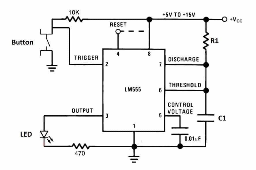
555 Timer Basics Monostable Mode To observe the monostable mode of the 555 timer, let’s build a simple one shot timer that will turn off an led after a certain length of time. use the diagram below to connect the circuit: r1: 10k ohms. r2: 10k ohms. r3: 470 ohms. c1: 470 μf. c2: 0.01 μf. in this circuit, after you press the button once, the led will light up then turn off. The 555 timer, designed by hans camenzind in 1971, can be found in many electronic devices starting from toys and kitchen appliances to even a spacecraft. it is a highly stable integrated circuit that can produce accurate time delays and oscillations. the 555 timer has three operating modes, bistable, monostable and astable mode.

555 Timer Monostable Circuit Diagram The following reference should help you understand the wiring concepts of a 555 timer. pin 1 – connected to ground (gnd vcc ) pin 2 – when voltage drops below 1 3 of vcc the trigger is activated. pin 3 – outputs up to 200 ma of current at ~1.5 volts. pin 4 – when connected to ground resets the timing operation of the output. A monostable 555 timer is required to produce a time delay within a circuit. if a 10uf timing capacitor is used, calculate the value of the resistor required to produce a minimum output time delay of 500ms. 500ms is the same as saying 0.5s so by rearranging the formula above, we get the calculated value for the resistor, r as:. The monostable multivibrator, or one shot, is one of the most basic 555 circuits. this circuit (figure 1) is part of the typical 555 datasheets, complete with the math needed to design to specification, and is one of the reasons a 555 is referred to as a timer. figure 1. schematic diagram of the 555 one shot timer with led output indicators. A monostable multivibrator using a 555 timer is a circuit that generates a single output pulse of a defined duration in response to an input trigger. this configuration of the 555 timer is also known as a one shot multivibrator because it returns to its stable state after a single pulse. the duration of the output pulse is determined by an rc.

Monostable 555 Timer Circuit Diagram The monostable multivibrator, or one shot, is one of the most basic 555 circuits. this circuit (figure 1) is part of the typical 555 datasheets, complete with the math needed to design to specification, and is one of the reasons a 555 is referred to as a timer. figure 1. schematic diagram of the 555 one shot timer with led output indicators. A monostable multivibrator using a 555 timer is a circuit that generates a single output pulse of a defined duration in response to an input trigger. this configuration of the 555 timer is also known as a one shot multivibrator because it returns to its stable state after a single pulse. the duration of the output pulse is determined by an rc. T is calculated below: t= 1.1 *100k * 10 uf = 1.1 seconds. you can also calculate the t with this 555 timer monostable calculator. above schematic diagram shows the 555 timer monostable multivibrator circuit. you can explore various applications based on monostable multivibrator in 555 timer circuits. Calculating output pulse duration. the output pulse duration (t) of a 555 monostable circuit is determined by the values of the timing resistor (r2) and the timing capacitor (c1) according to the following equation: t = 1.1 × r2 × c1. where: – t is the output pulse duration in seconds – r2 is the timing resistor value in ohms – c1 is.

Comments are closed.