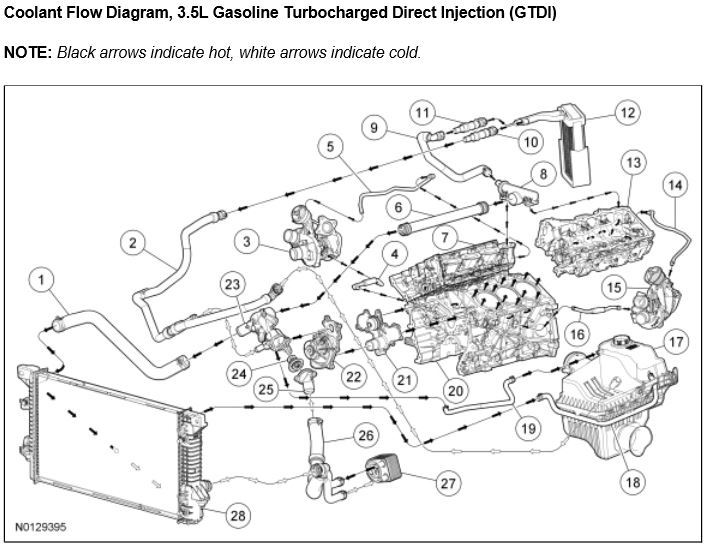
98 F150 Cooling System Diagram
Diagram 1998 Ford F 150 Cooling System Diagram Mydiagram Online The ford f150 4.6 cooling system consists of the radiator, water pump, thermostat, and coolant reservoir. coolant flows through hoses and passages, absorbing heat from the engine and carrying it to the radiator for cooling. the water pump circulates the coolant, while the thermostat controls its flow based on the engine’s temperature. Cooling system diagram. 02 f 150 supercrew xlt, 11 f 150 ecoboost lariat, 07 ranger, 01 supercrew, 98 supercab 4x4 other fords owned: 00 taurus, 96 t bird, 95.

1998 Ford F150 Cooling System Diagram Diagramwirings I need a diagram that shows the flow of the coolant through a 4.6 anyone got one? thanks in advance! basically, the water pump pushes water into the water jacket at the front of the motor, it travels down around the cylinders to the back of the motor, then up the back into the heads, and then to the front where it comes out the heads and goes. The cooling system is a vital component of any vehicle, and the ford f 150 is no exception. it is responsible for maintaining the engine’s temperature at an optimal level, preventing it from overheating and ensuring its longevity. the cooling system consists of several key parts, including the radiator, water pump, thermostat, hoses, and fan. Page 57 1998 f 150 250 workshop manual page 57 of 74 replace the 2wd vacuum solenoid. clear the dtcs. test the system for normal operation. c19 check circuit 145 (gy bk) for open gem c241 measure the resistance between gem c241 2, circuit 145 (gy bk), and 2wd vacuum solenoid c181, circuit 145 (gy bk). Overview of the ford f150 ac system. the ac system in the ford f150 is a crucial component for maintaining a comfortable driving experience, especially during hot summer months. it is responsible for cooling the interior of the vehicle and regulating the temperature to provide a pleasant atmosphere for the occupants. the ac system in the ford.
F150 Coolant System Diagram Page 57 1998 f 150 250 workshop manual page 57 of 74 replace the 2wd vacuum solenoid. clear the dtcs. test the system for normal operation. c19 check circuit 145 (gy bk) for open gem c241 measure the resistance between gem c241 2, circuit 145 (gy bk), and 2wd vacuum solenoid c181, circuit 145 (gy bk). Overview of the ford f150 ac system. the ac system in the ford f150 is a crucial component for maintaining a comfortable driving experience, especially during hot summer months. it is responsible for cooling the interior of the vehicle and regulating the temperature to provide a pleasant atmosphere for the occupants. the ac system in the ford. Page 6 1999 f 150 250 workshop manual page 6 of 30 a c vacuum check valve connect the a c vacuum check valve to a vacuum pump with two hoses and a tee fitting. apply 51 kpa (15 in hg) vacuum on the a c vacuum check valve and observe the gauge reading. if the vacuum loss exceeds 3.37 kpa (1 in hg) per minute, remove the a c vacuum check valve. And the engine’s cooling system does this smoothly. as the name suggests, the ford f150 cooling system diagram is a mechanism for cooling the ford f150’s engine with the help of water. it controls the engine’s temperature and does not let the heat get too high or too low. the water temperature gauge displayed in the meter indicates the.

Diagram 1998 Ford F 150 Cooling Diagram Mydiagram Online Page 6 1999 f 150 250 workshop manual page 6 of 30 a c vacuum check valve connect the a c vacuum check valve to a vacuum pump with two hoses and a tee fitting. apply 51 kpa (15 in hg) vacuum on the a c vacuum check valve and observe the gauge reading. if the vacuum loss exceeds 3.37 kpa (1 in hg) per minute, remove the a c vacuum check valve. And the engine’s cooling system does this smoothly. as the name suggests, the ford f150 cooling system diagram is a mechanism for cooling the ford f150’s engine with the help of water. it controls the engine’s temperature and does not let the heat get too high or too low. the water temperature gauge displayed in the meter indicates the.

Comments are closed.