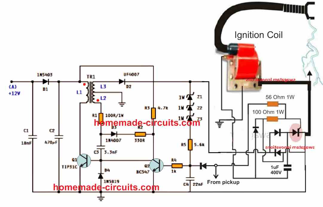
Ac Cdi Circuit Diagram

Cdi Unit Circuit Diagram The 6 pin cdi comes in the form of a black box fitted with a male connector up top. there are six different electrical pins inside of this connector that serve to provide power to the machine by syncing the various parts of the ignition system. these six pins connect the ignition power to the cdi, the ignition coil, the timing trigger or pulse. Simple capacitive discharge ignition (cdi) circuit.
Ac Cdi Techy At Day Blogger At Noon And A Hobbyist At Night The whole concept for this electronic cdi can be understood by studying the shown circuit diagram below: the diodes, the scr and the associated components form a standard cdi circuit. the high voltage of around 200v which needs to be fed to the above circuit is generated through an ordinary step down transformer connected the other way round. The 6 wires of a cdi connect the power, pickup trigger, ground, and ignition coil. trace each wire in the wiring diagram during troubleshooting. use a multimeter to test trigger, power, ground, and coil connections. know the spark generation sequence including signal trigger, amplification, energy storage and discharge. Stator wiring diagram. the stator is a key component that must be wired properly for the cdi system to work. here is a stator wiring diagram: the yellow wires go to the rectifier to be converted to dc charging voltage for the battery. there are usually two yellow wires. the white wires connect to the cdi box ac input. there should also be two. To build your own diy cdi ignition system, you will need a few key components. first, you will need a capacitor to store and discharge electrical energy. this capacitor will be charged by a source of high voltage power, such as a battery or generator. second, you will need a triggering device to initiate the discharge of the capacitor.

Cdi Unit Circuit Diagram Stator wiring diagram. the stator is a key component that must be wired properly for the cdi system to work. here is a stator wiring diagram: the yellow wires go to the rectifier to be converted to dc charging voltage for the battery. there are usually two yellow wires. the white wires connect to the cdi box ac input. there should also be two. To build your own diy cdi ignition system, you will need a few key components. first, you will need a capacitor to store and discharge electrical energy. this capacitor will be charged by a source of high voltage power, such as a battery or generator. second, you will need a triggering device to initiate the discharge of the capacitor. A cdi ignition schematic diagram is a visual representation of the electronic components and wiring involved in a capacitive discharge ignition system. it shows the connections and functions of the ignition coil, capacitor, battery, trigger circuit, and spark plug. this diagram is useful for understanding how a cdi ignition system works and troubleshooting any issues that may arise. The 5 pin cdi wiring diagram explained. a 5 pin cdi (capacitor discharge ignition) unit is an important component in the ignition system of many small engines, including motorcycles, dirt bikes, and atvs. it is responsible for generating the high voltage spark that ignites the fuel air mixture in the engine’s combustion chamber.

Ac Cdi Circuit Diagram A cdi ignition schematic diagram is a visual representation of the electronic components and wiring involved in a capacitive discharge ignition system. it shows the connections and functions of the ignition coil, capacitor, battery, trigger circuit, and spark plug. this diagram is useful for understanding how a cdi ignition system works and troubleshooting any issues that may arise. The 5 pin cdi wiring diagram explained. a 5 pin cdi (capacitor discharge ignition) unit is an important component in the ignition system of many small engines, including motorcycles, dirt bikes, and atvs. it is responsible for generating the high voltage spark that ignites the fuel air mixture in the engine’s combustion chamber.

Comments are closed.