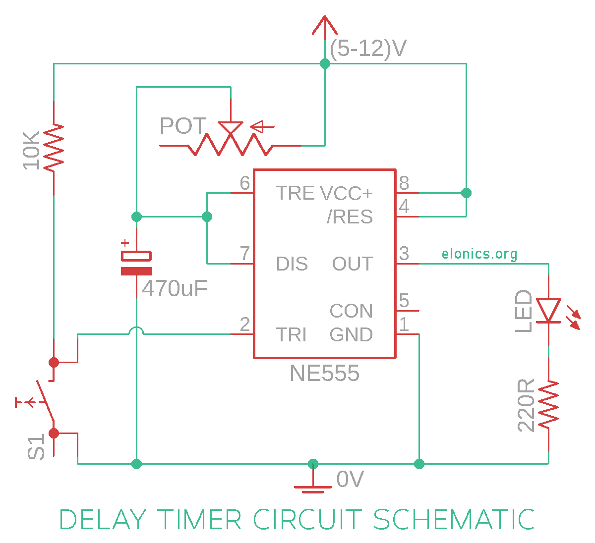
Adjustable Auto On Off Delay Timer Circuit On Breadboard 555 Timer Project 4

Adjustable Auto On Off Delay Timer Circuit On Breadboard о A tutorial on how to build an adjustable auto power on off delay timer circuit using 555 timer in monostable mode. this electronic timer circuit is helpful w. If the trigger pin (pin 2 of the 555 timer ic) senses any voltage less than 1 3rds of the supply voltage, it turns on the output. if the threshold pin (pin 6 of the 555 timer ic) senses any voltage more than 2 3rds of the supply voltage, it turns off the output. whenever the output of the 555 timer ic is in off state, the discharge pin (pin 7.

Adjustable Auto On Off Delay Timer Circuit Using 555 Ic Step 1: 555 timer ic in monostable mode. lets start by putting all the components together and lets understand how the circuit works. in the first example, i am going to show you guys the "on off timer circuit" with a fixed timing resistor and capacitor. the heart of this circuit is the 555 timer ic. A tutorial on how to make an adjustable delay timer circuit using 555 ic that can automatically turn on off any output after a fixed duration. this electroni. The 555 timer ic is an integrated circuit (ic) that is used in a variety of timer, delay, pulse generator and oscillator circuits. in this tutorial, i am going to show you guys how to make an "adjustable delay timer circuit" using the 555 timer ic. this circuit can automatically turn on off any circuit after a fixed duration. In this 555 timer project, i have shown how to make a time delay relay circuit using 555 timer ic to automatically turn off the switch after a predefined del.

555 Adjustable Delay On Off Timer Circuit R Breadboard The 555 timer ic is an integrated circuit (ic) that is used in a variety of timer, delay, pulse generator and oscillator circuits. in this tutorial, i am going to show you guys how to make an "adjustable delay timer circuit" using the 555 timer ic. this circuit can automatically turn on off any circuit after a fixed duration. In this 555 timer project, i have shown how to make a time delay relay circuit using 555 timer ic to automatically turn off the switch after a predefined del. 555 adjustable delay on off timer circuit. the 555 timer ic is an integrated circuit (ic) that is used in a variety of timer, delay, pulse generator and oscillator circuits. in this tutorial, i am going to show you guys how to make an "adjustable delay timer circuit" using the 555 timer ic. this circuit can automatically turn on off any circuit. The 555 timer delay before turn on circuit we will build is shown below. the breadboard schematic of the above circuit is shown below. to connect power to the 555 timer chip, we connect about 5 15v to v cc, pin 8 and we connect pin 1 to ground. we connect a 100μf capacitor to the positive voltage supply and then to pin 2.

Automatic On Off Delay Timer Circuit Using Ic 555 By Manmohan Pa 555 adjustable delay on off timer circuit. the 555 timer ic is an integrated circuit (ic) that is used in a variety of timer, delay, pulse generator and oscillator circuits. in this tutorial, i am going to show you guys how to make an "adjustable delay timer circuit" using the 555 timer ic. this circuit can automatically turn on off any circuit. The 555 timer delay before turn on circuit we will build is shown below. the breadboard schematic of the above circuit is shown below. to connect power to the 555 timer chip, we connect about 5 15v to v cc, pin 8 and we connect pin 1 to ground. we connect a 100μf capacitor to the positive voltage supply and then to pin 2.

Comments are closed.