Air Cooled Chiller Plant Diagram

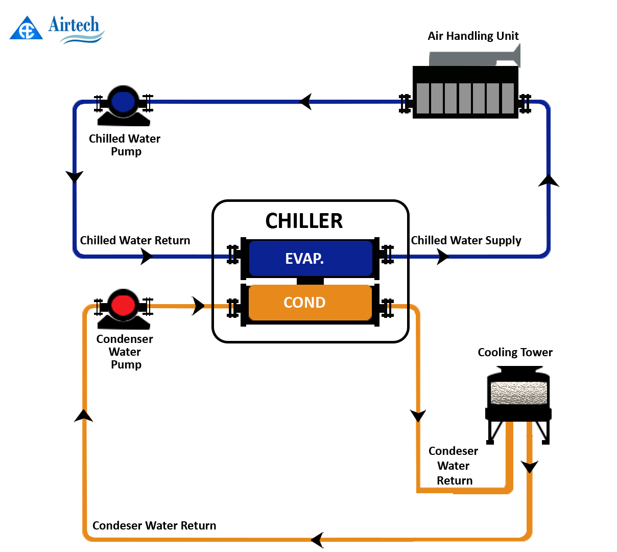
Air Cooled Chiller Schematic Diagram Chilled water schematic and condenser water schematic, how to read and understand the engineering drawings with real world examples, illustrations, animations and video tutorial. covering chillers, pump sets, ahus, risers, primary and secondary systems, cooling towers and bypass lines. This video guides you through the basic operation of a chiller, making use of animations, illustrations, 3d models and real world photographs to help build y.

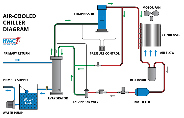
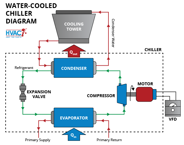
Air Cooled Chiller How They Work Working Principle Chiller Basics A chiller is made up of the 4 major components required for the refrigeration process which are: a) compressor, b) condenser, c) evaporator and d) expansion valve. to produce chilled water, the refrigerant absorbs heat from the water and thus, chilling the water to about 6.7°c (44°f). Figure 27 mcquay air cooled screw chiller. many small to medium chiller plants use air cooled chillers with air cooled screw chillers being common in the 150 to 400 ton range. air cooled screw chillers offer very good performance particularly at part load. the compressors are modulating rather than stepped which provides more accurate control. The air cooled condenser is a heat exchanger where the process heat absorbed by the refrigerant is given off to the air around it. as heat is given off by the high temperature high pressure vapor, its temperature falls until the vapor condenses to a liquid. a centrifugal blower or motor driven fans generate airflow across the condenser. The chillers will produce “chilled water” which is pumped out around the building to the air handling units (ahu’s) and fan coil units (fcu’s) which remove the unwanted heat from the building and transfer it into the chilled water loop. the chilled water will enter the ahu’s fcu’s at around 6°c (42.8°f) and by the time it leaves.

Air Cooled Chiller Schematic Diagram The air cooled condenser is a heat exchanger where the process heat absorbed by the refrigerant is given off to the air around it. as heat is given off by the high temperature high pressure vapor, its temperature falls until the vapor condenses to a liquid. a centrifugal blower or motor driven fans generate airflow across the condenser. The chillers will produce “chilled water” which is pumped out around the building to the air handling units (ahu’s) and fan coil units (fcu’s) which remove the unwanted heat from the building and transfer it into the chilled water loop. the chilled water will enter the ahu’s fcu’s at around 6°c (42.8°f) and by the time it leaves. The unwanted heat is removed from the condenser using fans which blow cooler ambient air across the condenser coil. in this example the fans will have total volume flow rate of 30.75 cubic meters per second (30,750 liters per second). the air temperature going in is around 30°celsius (86°f) and the temperature out will be around 44°c (111°f). An air cooled chiller piping system is a critical component of an air conditioning system. it is responsible for circulating the coolant, also known as refrigerant, throughout the chiller unit to absorb and dissipate heat. a well designed piping system ensures efficient operation and optimal cooling performance.

Chiller Chiller Machine Water Chiller Plant Air Chiller Screw The unwanted heat is removed from the condenser using fans which blow cooler ambient air across the condenser coil. in this example the fans will have total volume flow rate of 30.75 cubic meters per second (30,750 liters per second). the air temperature going in is around 30°celsius (86°f) and the temperature out will be around 44°c (111°f). An air cooled chiller piping system is a critical component of an air conditioning system. it is responsible for circulating the coolant, also known as refrigerant, throughout the chiller unit to absorb and dissipate heat. a well designed piping system ensures efficient operation and optimal cooling performance.

Comments are closed.