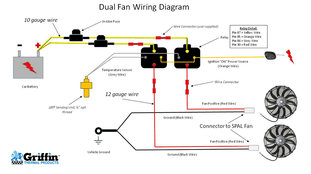
Be Cool Dual Fan Wiring Diagram

Diagram Elec Wiring Diagrams Dual Fans Mydiagram Online Instructions for be cool kit part #75096gray wire: connect the gray wire from the relay to the temperature sendin. unit using the enclosed butt connector.black wire: connect the black wire to the eyelet. onnector and then to the chassis ground.connect a high amp toggle switch (be cool kit #75096) to th. Price: $129.99. description. packaging. specs. wiring an electric fan can be easy when you install a be cool wiring harness that we manufacture in house. our dual fan wiring harnesses come complete with the proper gauge and color coordinated wire, a temperature sending unit, waterproof 40 amp relays, and a 30 amp fuse with fuse holder.

Cooling Fan Wiring Diagram Auto Page 5: installation instructions. green wire: connect the green wire from the relay to the ignition terminal in fuse box. for air conditioned vehicles, use be cool kit #75095. when air conditioning is activated, fans will turn on regardless of engine temperature. wiring instructions for optional a c wiring harness kit be cool part #75095 blue. Optionally, a single high current relay could be used to control both fans. the supplied diagram below using dual relays with a single temp sensor is both the most reliable and easiest method we've found for wiring dual fans. it uses our 40 amp electric relay kit and electric fan sensor. the relay isolates the high amp load of the fan circuit. The fan should be mounted as high on the radiator core as possible. the spacing between the radiator and the electric fan should be approximately 3 8" to maintain air flow through the core. the best results are obtained by using be cool fan mounting. do not attach through the radiator core, use the radiator flanges where there is a metal lip. Start your wiring project by taking both of the positive wires from the fans and run them to the yellow wires on each relay (tab 87). then connect switched power (usually from your ignition switch), to the blue wires on both relays (tab 86). next, splice together both black wires from the relays (tab 85) and connect them to the thermostat switch.

Comments are closed.