Clock Circuit Using 555 Timer Ic

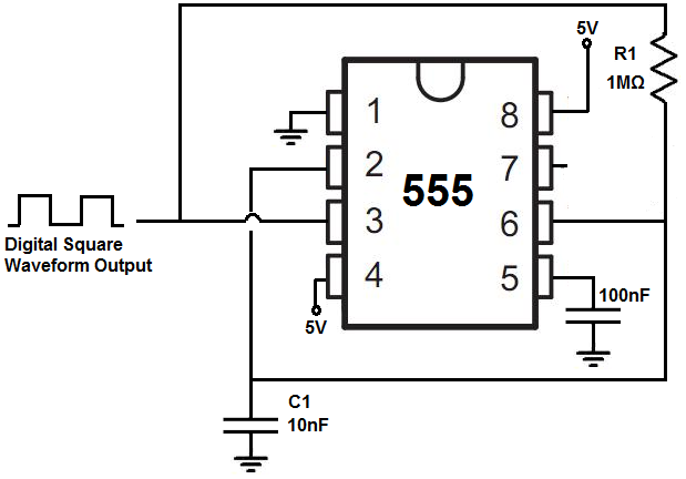
How To Build A Clock Circuit With A 555 Timer The clock circuit that will produce 60hz clock signals using a 555 timer is shown below. the breadboard schematic of the above circuit is shown below. this 555 timer is in astable mode. astable mode can produce digital square waveforms that go back and forth between high and low. so we have a signal with a frequency of about 60hz. A 555 timer can give out only 100 to 200 ma in total. check your chip’s datasheet for the exact value. this pin resets the whole circuit. it’s an “inverted” pin, which means it resets when the pin goes low. this means the pin must be high normally so that the chip isn’t in a “reset” state.

Digital Clock Circuit Using 555 Timer Diagram Here’s the internal schematics of 555 timer which consists of 25 transistors, 2 diodes and 15 resistors. represented with a block diagram it consists of 2 comparators, a flip flop, a voltage divider, a discharge transistor and an output stage. the voltage divider consists of three identical 5k resistors which create two reference voltages at. When it comes to interesting projects, building a digital clock circuit using a 555 timer is a great option. a 555 timer is an integrated circuit that can be used for a variety of tasks, including timing delays, measuring frequency and creating pulse width modulation. the 555 timer is a great choice for beginners because it’s easy to. To create a digital clock circuit diagram using a 555 timer, we will need a few additional components. these include a 7 segment display, which is used to display the digits of the time, and a few resistors and capacitors to set the frequency of the clock. additionally, we will need a power supply to power the circuit. 555 circuits part 1 – the fastest 555 oscillator. by varying the value of either r or c the 555 astable multivibrator circuit can be made to oscillate at any desired output frequency. but what is the maximum frequency of oscillations we can produce from a single 555 timer chip. to get the 555 to operate at its highest frequency in this 555.

Digital Clock Circuit Diagram Using 555 Timer To create a digital clock circuit diagram using a 555 timer, we will need a few additional components. these include a 7 segment display, which is used to display the digits of the time, and a few resistors and capacitors to set the frequency of the clock. additionally, we will need a power supply to power the circuit. 555 circuits part 1 – the fastest 555 oscillator. by varying the value of either r or c the 555 astable multivibrator circuit can be made to oscillate at any desired output frequency. but what is the maximum frequency of oscillations we can produce from a single 555 timer chip. to get the 555 to operate at its highest frequency in this 555. A monostable 555 timer is required to produce a time delay within a circuit. if a 10uf timing capacitor is used, calculate the value of the resistor required to produce a minimum output time delay of 500ms. 500ms is the same as saying 0.5s so by rearranging the formula above, we get the calculated value for the resistor, r as:. Synchronous circuit timer. a synchronous circuit is a digital circuit in which the changes in the state of memory elements, commonly flip flops, are synchronized by a clock signal. because of their availability and ease of use, the 555 astable circuit is the common source of clock signal in many synchronous circuits.

Comments are closed.