Contactless Ac Current Tester 555 Timer Ic Easy And Useful Project

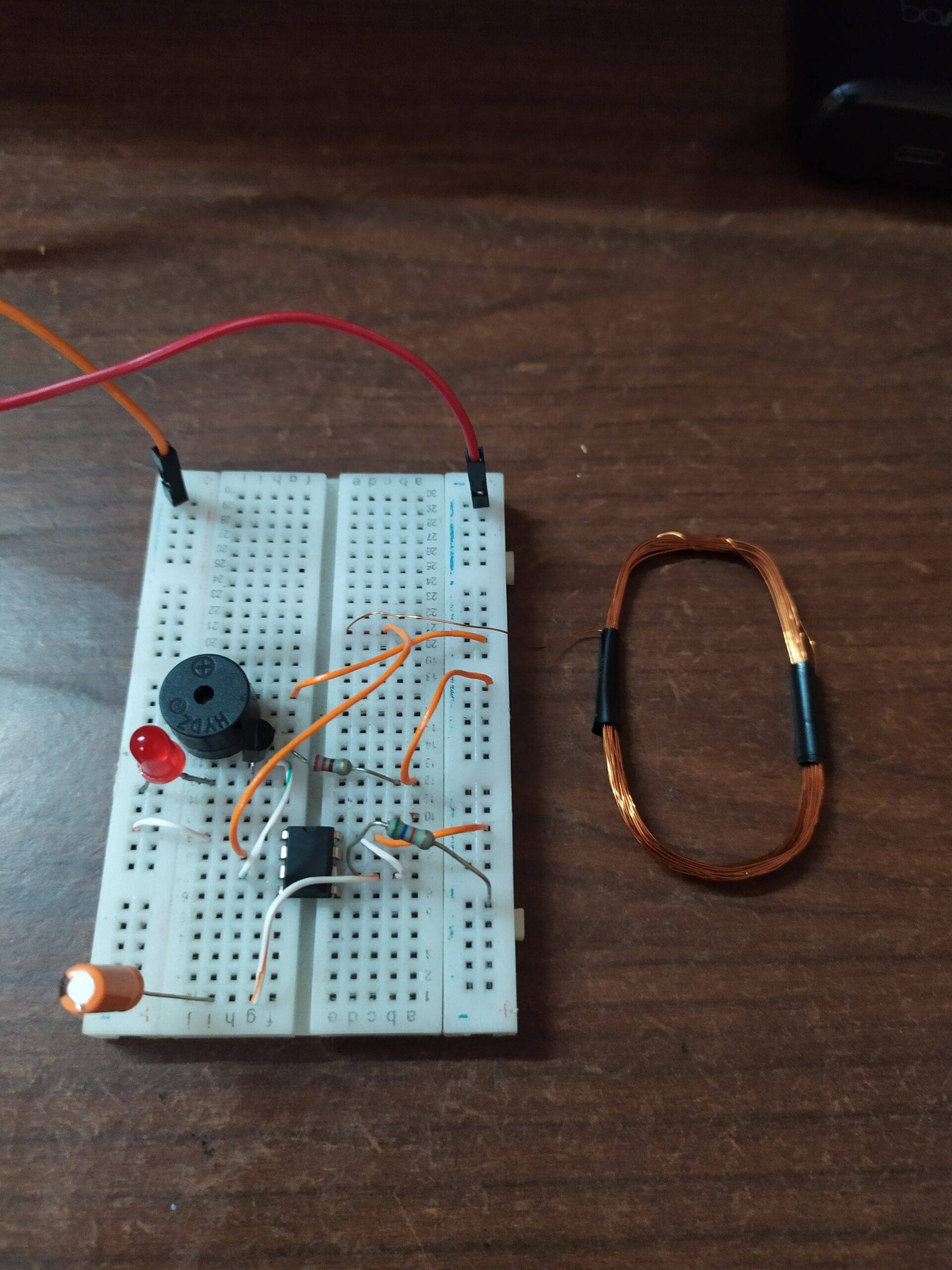
Contactless Ac Current Tester 555 Timer Ic Easy And Useful Project Hey guys, welcome back to prabha's creative experiments. have you ever seen a current detector used to find the flow of electric current in the wires? someti. In the 2nd setup i am using the 555 timer ic. 555 timer is the most common chip used in diy electronics projects because it’s small, inexpensive, and very useful. this circuit is very simple. when the voltage on pin 2 falls below 1⁄3 of vcc the output on pin 3 goes high and the led lights up.

Simple 555 Timer Ic Testing Circuit Working Principle About the current detector 555 circuit. the 555 timer ic has a total of 8 pins, 4 pins on one side. you can identify the pin number by viewing its datasheet or the notch which is marked on the ic. pin number 1 is ground and 8 is vcc. take a current carrying wire like a dc adapter and bring it near to the antenna of the current detector circuit. 555 timer ic pinout. the pinout of the 555 timer ic is shown below the. gnd the ground pin gets connected to supply ground. trigger responsible for transition of the flip flop from set to reset. the output of the timer depends 2 i on the amplitude of the external trigger pulse applied to this pin. output this pin is normally connected to load. Step 3: setup using ic 555. in the 2nd setup i am using the 555 timer ic.555 timer is the most common chip used in diy electronics projects because it’s small, inexpensive, and very useful. this circuit is very simple. when the voltage on pin 2 falls below 1⁄3 of vcc the output on pin 3 goes high and the led lights up. Step 3: setup using ic 555. in the 2nd setup i am using the 555 timer ic. 555 timer is the most common chip used in diy electronics projects because it’s small, inexpensive, and very useful. this circuit is very simple. when the voltage on pin 2 falls below 1⁄3 of vcc the output on pin 3 goes high and the led lights up.

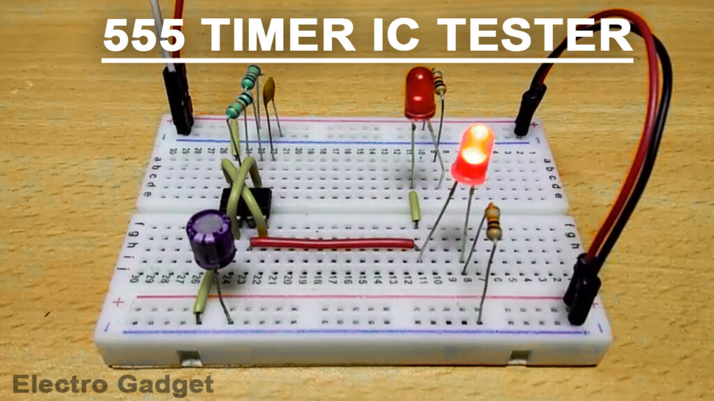
555 Timer Ic Tester Engineering Projects Step 3: setup using ic 555. in the 2nd setup i am using the 555 timer ic.555 timer is the most common chip used in diy electronics projects because it’s small, inexpensive, and very useful. this circuit is very simple. when the voltage on pin 2 falls below 1⁄3 of vcc the output on pin 3 goes high and the led lights up. Step 3: setup using ic 555. in the 2nd setup i am using the 555 timer ic. 555 timer is the most common chip used in diy electronics projects because it’s small, inexpensive, and very useful. this circuit is very simple. when the voltage on pin 2 falls below 1⁄3 of vcc the output on pin 3 goes high and the led lights up. Friends in this circuit we will use a 555 timer ic and some simple components for making the non contact voltage tester circuit. components pcb board555 ic. Block diagram of darlington transistor circuit. here is a step by step process. #1 the antenna inducts very little electrical energy or ac main signal that frequency of 50hz (60hz) into b of q1. #2 makes a higher current flow through r1, c to e of q1. #3 next a higher current flow through r2, c to e of q2.

Current Detector 555 Timer Project Current Detector 555 Circuit Friends in this circuit we will use a 555 timer ic and some simple components for making the non contact voltage tester circuit. components pcb board555 ic. Block diagram of darlington transistor circuit. here is a step by step process. #1 the antenna inducts very little electrical energy or ac main signal that frequency of 50hz (60hz) into b of q1. #2 makes a higher current flow through r1, c to e of q1. #3 next a higher current flow through r2, c to e of q2.

Comments are closed.