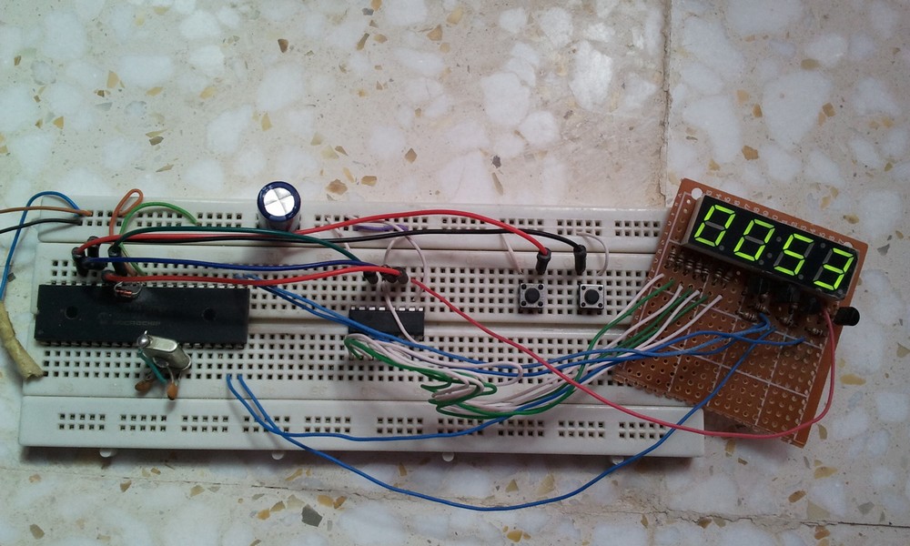
Controlling Segment Display Using Arduino And 74hc595 54 Off

Controlling Seven Segment Display Using Arduino And 74hc595 5 So for a 4 digit 7 segment display we need just 6 pins: clock, data and 4 common pins (each digit has its individual common pin). this post shows how to build a simple digital counter using arduino, common anode 7 segment display with 4 digits, and 74hc595 shift register. to see how to interface the arduino with 7 segment display without shift. Learn how to control a 1 digit seven segment display with a shift register! 1const int latchpin =13; latch pin of the 74hc5952const int clockpin =12; clock pin of the 74hc5953const int datapin =8; data pin of the 74hc5954 byte leds =0; byte variable that holds which led is turned on at a time5 int repeatnum =300; number of times to repeat.

Controlling Seven Segment Display Using Arduino And 74hc595 5 When i search for ways to control a 4 digit 7 segment display with arduino, i find countless threads and tutorials using a 74hc595. the worst of these use one 74hc595 per digit. the best use a single 74hc595 for all digits, plus transistors to turn individual digits on and off. but even the best eat up a lot of arduino pins (example: lesson 28 4 digit 7 segment display ). are there. A standard 4 digit 7 segment display is needed for clock, timer and counter projects, but it usually requires 12 connections. the 74hc595 module makes it easier by only requiring 5 connections: 2 for power and 3 for controlling the segments. this tutorial will not overload you by deep driving into hardware. It is an active high pin hence when kept at low it will enable the ic to give outputs. 4) connect arduino pin 2 to pin12 (latch pin) of the ic. 5) connect arduino pin 3 to pin14 (data pin) of the ic. 6) connect arduino pin 4 to pin11 (clock pin) of the ic. 7) connect vcc and gnd of the ic to that of the arduino. The 74hc575 is an 8 stage serial shift register that also has an internal storage register. the storage register buffers the output data and can be clocked independently of the shift register. this prevents the data from changing while it is being loaded. the 74hc595 has a “3 state” output.

Controlling Segment Display Using Arduino And 74hc595 54 о It is an active high pin hence when kept at low it will enable the ic to give outputs. 4) connect arduino pin 2 to pin12 (latch pin) of the ic. 5) connect arduino pin 3 to pin14 (data pin) of the ic. 6) connect arduino pin 4 to pin11 (clock pin) of the ic. 7) connect vcc and gnd of the ic to that of the arduino. The 74hc575 is an 8 stage serial shift register that also has an internal storage register. the storage register buffers the output data and can be clocked independently of the shift register. this prevents the data from changing while it is being loaded. the 74hc595 has a “3 state” output. About the project. this is a project that i decided to try out. it uses a 74hc595 shift register to control a 7 segment display. it needs three digital pins and 5v and ground pins from the arduino. i tried this project because i was running out of digital pins on my arduino uno. Code explanation: the first step is to define the three control pins of the 74hc595, namely the latch, clock, and data pin, which are connected to the arduino’s digital pins #5, #6, and #4, respectively. int latchpin = 5; int clockpin = 6; int datapin = 4; next, a variable called leds of datatype byte is defined.

Comments are closed.