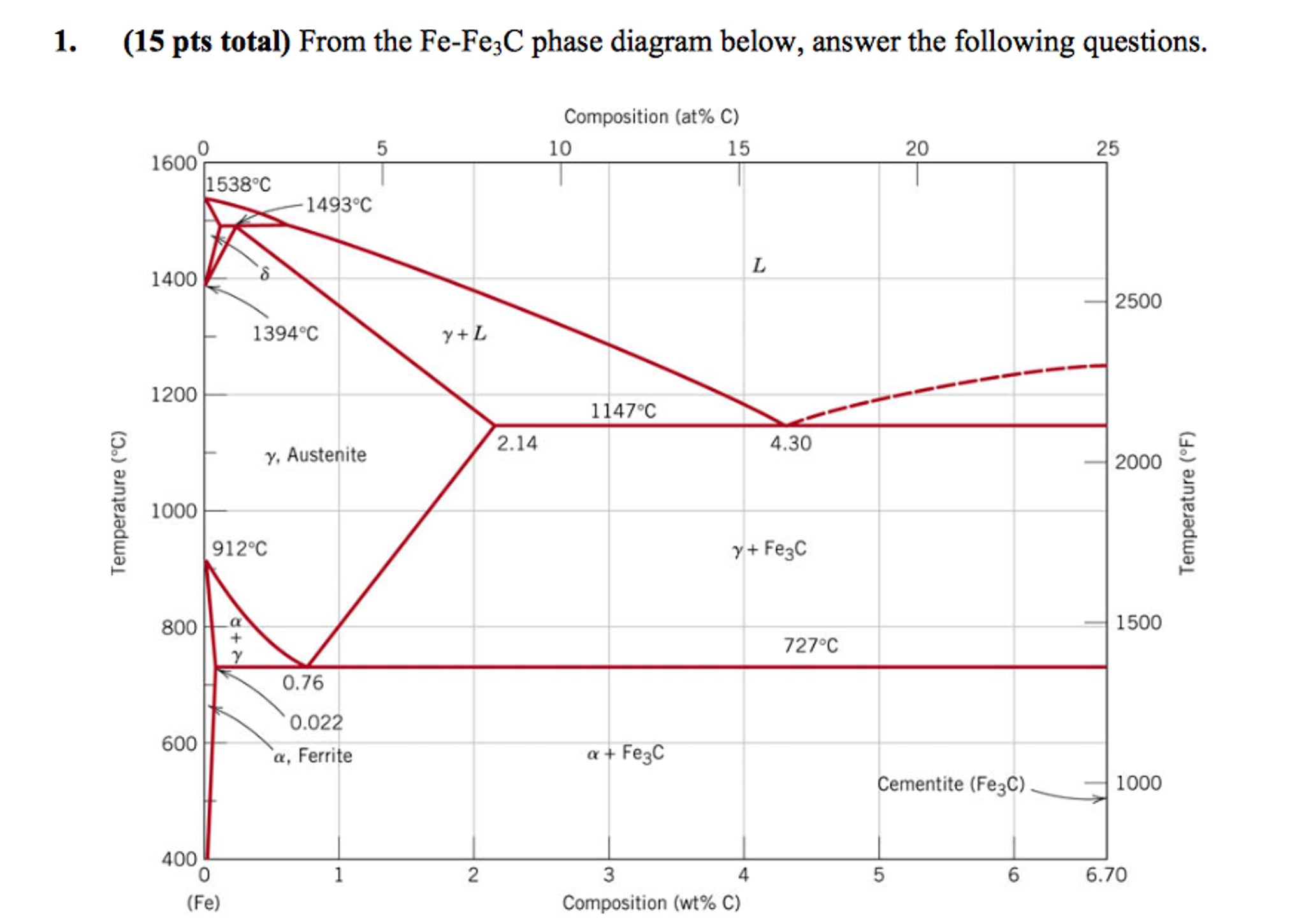
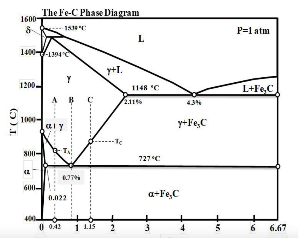
Cooling Alloys Fe C Phase Diagram

Fe C Phase Diagram And Microstructures Download Scientific Diagram The fe c phase diagram is primarily composed of two elements: iron (fe) and carbon (c). it showcases the different phases that occur when different concentrations of carbon are added to iron. the diagram consists of a temperature axis and a carbon concentration axis. on the left side of the diagram, we have pure iron, known as the α iron phase. The fe c phase diagram is a fundamental tool in materials science and engineering that provides crucial insights into the behavior and properties of iron carbon alloys. this diagram showcases the different phases present in these alloys at varying temperatures and carbon compositions, allowing scientists and engineers to design and manipulate.

Fe C Phase Diagram Explained Summary. phase diagrams are useful tools to determine: the number and types of phases, the wt% of each phase, and the composition of each phase. for a given t and composition of the system. alloying to produce a solid solution usually. increases the tensile strength (ts) decreases the ductility. binary eutectics and binary eutectoids. For example, the water phase diagram describes a point (triple point) where water can coexist in three different phases at the same time. this happens at just above the freezing temperature (0.01°c) and 0.006 atm. using the diagrams. there are four major uses of alloy phase diagrams: development of new alloys based on application requirements. A metastable iron carbon phase diagram is used to emphasize the fact that the iron carbon relationship is metastable due to the slow cooling rates of iron alloys. in the term “fe c phase diagram,” fe c is shorthand for iron carbon. the diagram is also known as a “steel phase diagram” since iron alloys are steel. Summary. phase diagrams are useful tools to determine: the number and types of phases, the wt% of each phase, and the composition of each phase. for a given t and composition of the system. alloying to produce a solid solution usually. increases the tensile strength (ts) decreases the ductility.

Fe C Phase Diagram A metastable iron carbon phase diagram is used to emphasize the fact that the iron carbon relationship is metastable due to the slow cooling rates of iron alloys. in the term “fe c phase diagram,” fe c is shorthand for iron carbon. the diagram is also known as a “steel phase diagram” since iron alloys are steel. Summary. phase diagrams are useful tools to determine: the number and types of phases, the wt% of each phase, and the composition of each phase. for a given t and composition of the system. alloying to produce a solid solution usually. increases the tensile strength (ts) decreases the ductility. The fe c diagram, also known as the iron carbon phase diagram, is a critical tool in understanding the behavior and properties of iron and steel. it provides valuable information about the phases and transformations that occur during the cooling and heating of iron carbon alloys. one of the key features of the fe c diagram is the presence of. C is an interstitial impurity in fe. it forms a solid solution with α, γ, δ phases of iron. maximum solubility in bcc α ferrite is limited (max. 0.022 wt% at 727 °c) bcc has relatively small interstitial positions. maximum solubility in fcc austenite is 2.14 wt% at 1147 °c fcc has larger interstitial positions.

Comments are closed.