Cooling Tower Equalizing Line Diagram

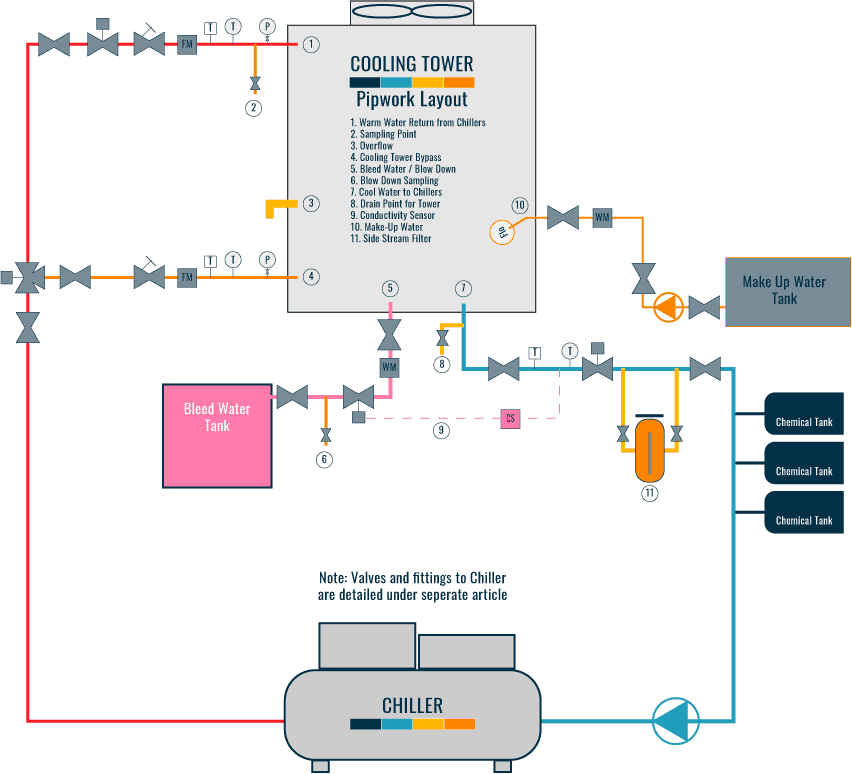
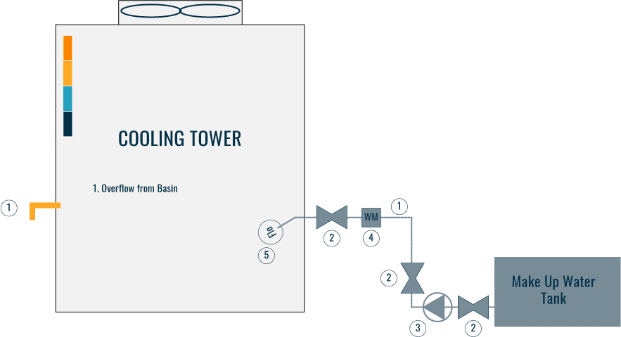
Cooling Tower Piping Layout And Diagrams Constructandcommission An external equalizer is a piped connection, specifically sized to maintain equal water levels between multiple cells or multiple units for an open cooling tower system. equalizers must be used when two or more cooling towers are piped with a common header. the equalizer lines must be properly sized for 15% of the largest cooling tower flowrate. Cooling tower | piping layout and diagrams. to allow the cooling towers to operate correctly, in line with the design and efficiently, various systems will need to be connected to allow them to work. depending upon how the towers are installed will mean different configurations would be required. the pipework that is commonly connected to the.

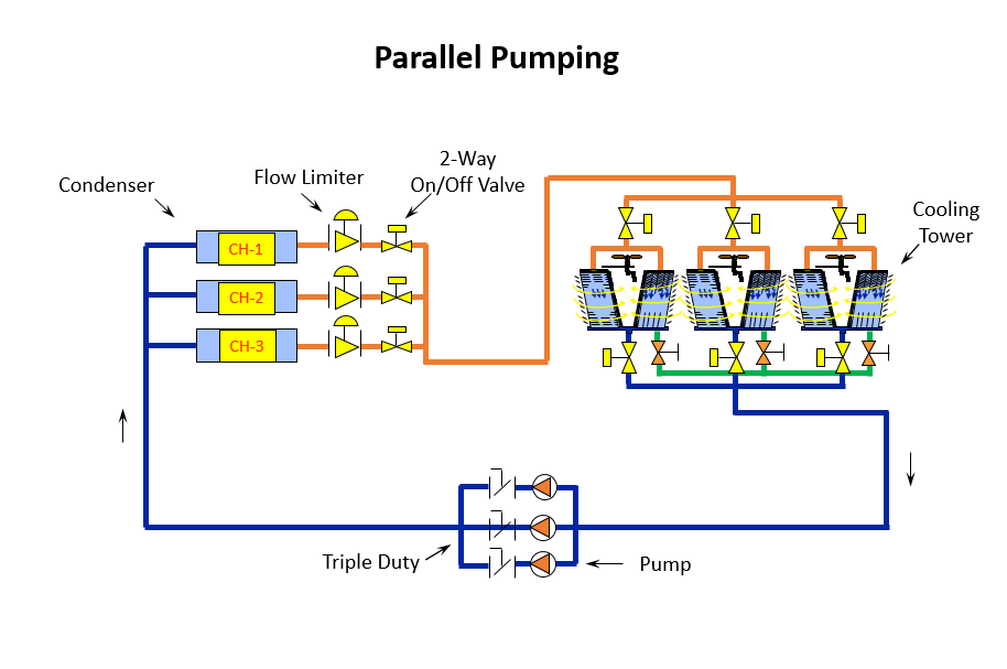
Parallel Pumping 2 Position Control Valves On Multiple Cooling Towers Design capacity – 430.0 gpm design head – 47.0 feet motor size – 10 hp. less than anticipated pump headthe pump point shift has increased flow. over design to the order of 45%. cavitational and or tower vortex can occur unless. corrective measures are applied.the pump impeller diameter could, and should be cut down. Product: cooling towers – free cooling operation date: april 16, 2010 table of contents section page i. introduction background 2 ii. system design considerations: cooling tower selection 5 unit layout 6 cooling tower piping 7 cooling tower accessories 8 iii. capacity control methods 10. Section 1 – evaporative cooling towers an evaporative cooling tower is a heat exchanger that transfers heat from circulating water to the atmosphere. warm water from the heat source is pumped to the top of the tower and then flow down through plastic or wooden shells. as it falls downward . cooling towers – m07 001 3. A cooling tower, approximately 1% of the total flow is evaporated for each 10°f (6.9°c) temperature change. range and approach are two important terms used in the discussion of cooling towers (see sidebar, cooling tower terminology, page 53). the performance of a cooling tower is a function of the ambient wet bulb temperature, entering water.

Cooling Tower Diagram A Go To Guide To Learn About Section 1 – evaporative cooling towers an evaporative cooling tower is a heat exchanger that transfers heat from circulating water to the atmosphere. warm water from the heat source is pumped to the top of the tower and then flow down through plastic or wooden shells. as it falls downward . cooling towers – m07 001 3. A cooling tower, approximately 1% of the total flow is evaporated for each 10°f (6.9°c) temperature change. range and approach are two important terms used in the discussion of cooling towers (see sidebar, cooling tower terminology, page 53). the performance of a cooling tower is a function of the ambient wet bulb temperature, entering water. De energize the fan(s) for two full minutes before reversing. reverse fan(s) no more than 2 minutes at a time (repeat as necessary). extended reverse operation can cause ice to form on fan blades causing an out of balance condition. if the tower is equipped with a two speed motor, reverse only at low speed. Select a pipe size and entering 120 gpm in the “flow pressure drop” tab. go to the “length pressure drop” tab and click on the help with tel button and enter the pipe length and fittings. change the pipe size until the pressure drop is less than .0833 feet. the result was that an 8” pipe should be used for the equalizing line.

Cooling Tower Piping Layout And Diagrams Constructandcommission De energize the fan(s) for two full minutes before reversing. reverse fan(s) no more than 2 minutes at a time (repeat as necessary). extended reverse operation can cause ice to form on fan blades causing an out of balance condition. if the tower is equipped with a two speed motor, reverse only at low speed. Select a pipe size and entering 120 gpm in the “flow pressure drop” tab. go to the “length pressure drop” tab and click on the help with tel button and enter the pipe length and fittings. change the pipe size until the pressure drop is less than .0833 feet. the result was that an 8” pipe should be used for the equalizing line.

Comments are closed.