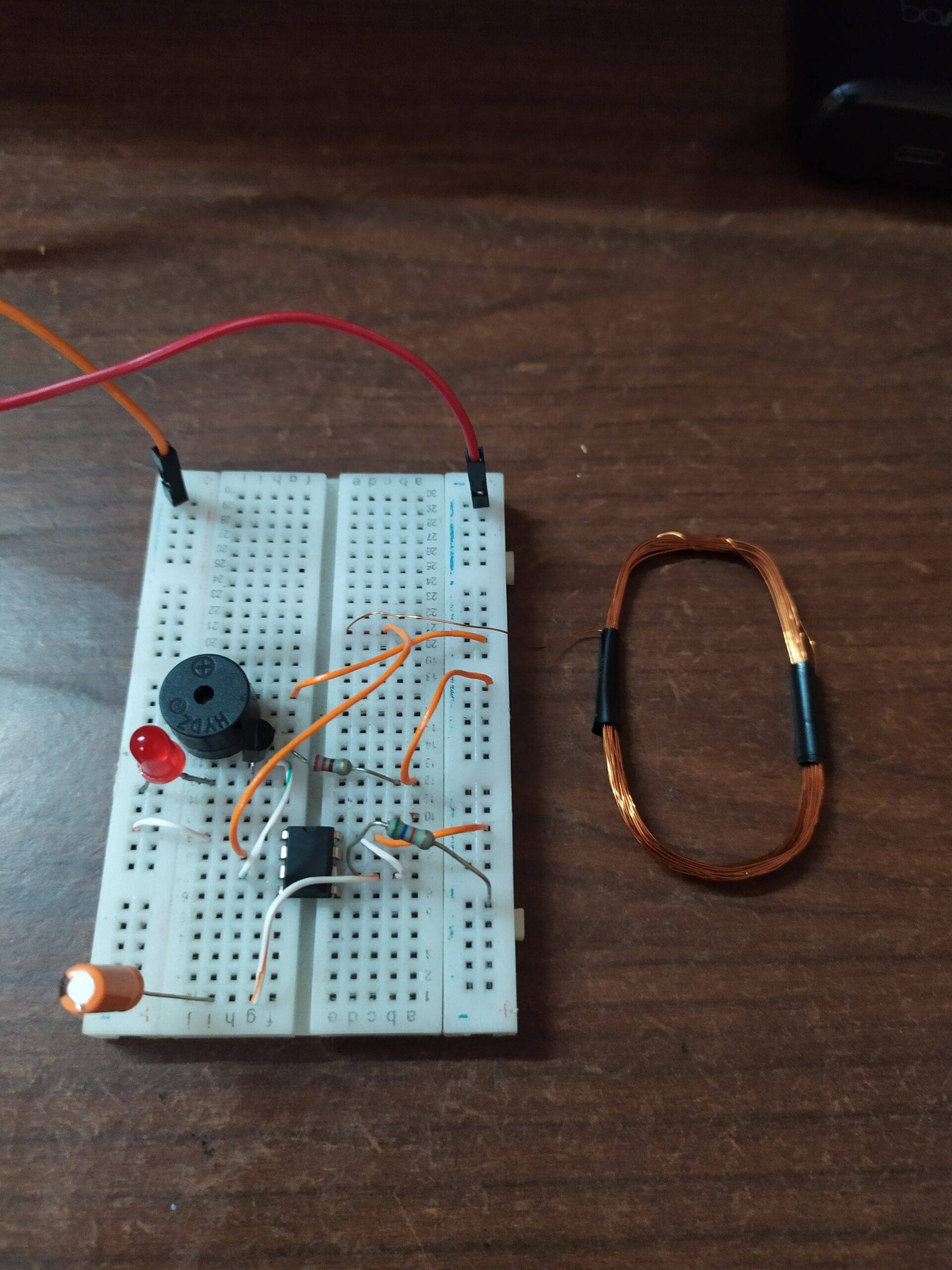
Current Detector Circuit Using 555 Ic Ac Current Tester 555 Ac Current Detector Sensor Make

Current Detector Circuit Using 555 Ic Ac Current About the current detector 555 circuit. the 555 timer ic has a total of 8 pins, 4 pins on one side. you can identify the pin number by viewing its datasheet or the notch which is marked on the ic. pin number 1 is ground and 8 is vcc. take a current carrying wire like a dc adapter and bring it near to the antenna of the current detector circuit. Circuit diagram. the 555 timer is the most commonly used ic for many different applications, which is what the working of the circuit is very simple when the voltage at pin 2 falls below ⅓ of the vcc the output pin of the 555 timer goes high and the led lights up and when its above ⅓ vcc the output goes low and the led shuts down.

Current Detector Circuit Using With Ic 555 Youtube Buy electronic component from here: electronicspices please check our new channel & give the review and suggestions. Current detector circuit using 555 ic | ac current tester | non contact ac dc current detector#currentdetector #technicalsuccess #tester #wirelesstester. Current detector circuit using 555 ic | ac current tester | 555 ac current detector sensor makeif you have enjoyed this video then please like, comment and d. For this circuit, we will select the vishay wslp59312l000fea current sense resistor. this is a 2 mohm, 8w, 1% tolerance current sense resistor. let's say we are working with a battery management system that is designed for a maximum of 62.5a. doing the math, power= i 2 r= 7.8125w.

Current Detector 555 Timer Project Current Detector 555 Circu Current detector circuit using 555 ic | ac current tester | 555 ac current detector sensor makeif you have enjoyed this video then please like, comment and d. For this circuit, we will select the vishay wslp59312l000fea current sense resistor. this is a 2 mohm, 8w, 1% tolerance current sense resistor. let's say we are working with a battery management system that is designed for a maximum of 62.5a. doing the math, power= i 2 r= 7.8125w. Last updated on march 16, 2024. a simple noncontact ac line detector circuit is designed by using famous timer ic 555, this circuit uses a coil to detect tiny electromagnetic field and triggers the timer ic 555 to produce timing pulse at output. connected led will blink if the coil detects electromagnetic field around ac supply flowing cable. Step 1: connecting the transistors. describing this step is very laborious. the images make it a lot clearer! bend the collector of transistor 1 ninety degrees. bend the base of transistor 1 all the way over the transistor. bend the collector of transistor 2 ninety degrees. connect the emitter from transistor 1 to the base of transistor 2.

Comments are closed.