Current Tester Using 555 Timer Ic

Simple 555 Timer Tester Circuit Youtube 555 timer ic pinout. the pinout of the 555 timer ic is shown below the. gnd the ground pin gets connected to supply ground. trigger responsible for transition of the flip flop from set to reset. the output of the timer depends 2 i on the amplitude of the external trigger pulse applied to this pin. output this pin is normally connected to load. About the current detector 555 circuit. the 555 timer ic has a total of 8 pins, 4 pins on one side. you can identify the pin number by viewing its datasheet or the notch which is marked on the ic. pin number 1 is ground and 8 is vcc. take a current carrying wire like a dc adapter and bring it near to the antenna of the current detector circuit.

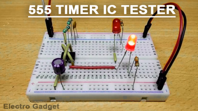
555 Timer Ic Tester Engineering Projects This simple 555 ic testing circuit can be used to test your entire 555 timer ic collection. so, before using your ic in any project, make sure that your ic is good or bad by testing it. this can be done by configuring the ic to act as an oscillator i.e. 555 is configured in astable mode of operation. the 555 tester circuit will rapidly tell you. Buy electronic component from here: electronicspices please check our new channel & give the review and suggestions. The 555 timer ic is working in an astable multivibrator mode. there are two probes used marked as testing probes, they are placed on the circuit where you want to check the connections and wires, these probes will detect the current flowing through them. attach two wires like multimeter wire types with these two testing points to check the. Step 1: gathering the parts. parts and cautions. depending on your hearing or what you find best as far as the sound produced by the output, you will need to figure out what resistors and capacitor you wish to use for the timer section of the circuit. this is an astable multivibrator circuit. when the switch is closed, the output is a square.

Simple 555 Timer Ic Testing Circuit Working Principle The 555 timer ic is working in an astable multivibrator mode. there are two probes used marked as testing probes, they are placed on the circuit where you want to check the connections and wires, these probes will detect the current flowing through them. attach two wires like multimeter wire types with these two testing points to check the. Step 1: gathering the parts. parts and cautions. depending on your hearing or what you find best as far as the sound produced by the output, you will need to figure out what resistors and capacitor you wish to use for the timer section of the circuit. this is an astable multivibrator circuit. when the switch is closed, the output is a square. Hey guys, welcome back to prabha's creative experiments. have you ever seen a current detector used to find the flow of electric current in the wires? someti. 555 lab introduction to the 555 timer ic. in this collection of hands on electronics experiments, build and test mixed signal analog and digital circuits using the versatile 555 timer ic. these projects will teach you about rc time constants, duty cycle, transistor current drive, leds, voltage doublers, and more.

Solved Multisim Circuit Design With A 555 Timer Solveforum Hey guys, welcome back to prabha's creative experiments. have you ever seen a current detector used to find the flow of electric current in the wires? someti. 555 lab introduction to the 555 timer ic. in this collection of hands on electronics experiments, build and test mixed signal analog and digital circuits using the versatile 555 timer ic. these projects will teach you about rc time constants, duty cycle, transistor current drive, leds, voltage doublers, and more.

Comments are closed.