Dc Cdi Circuit Diagram

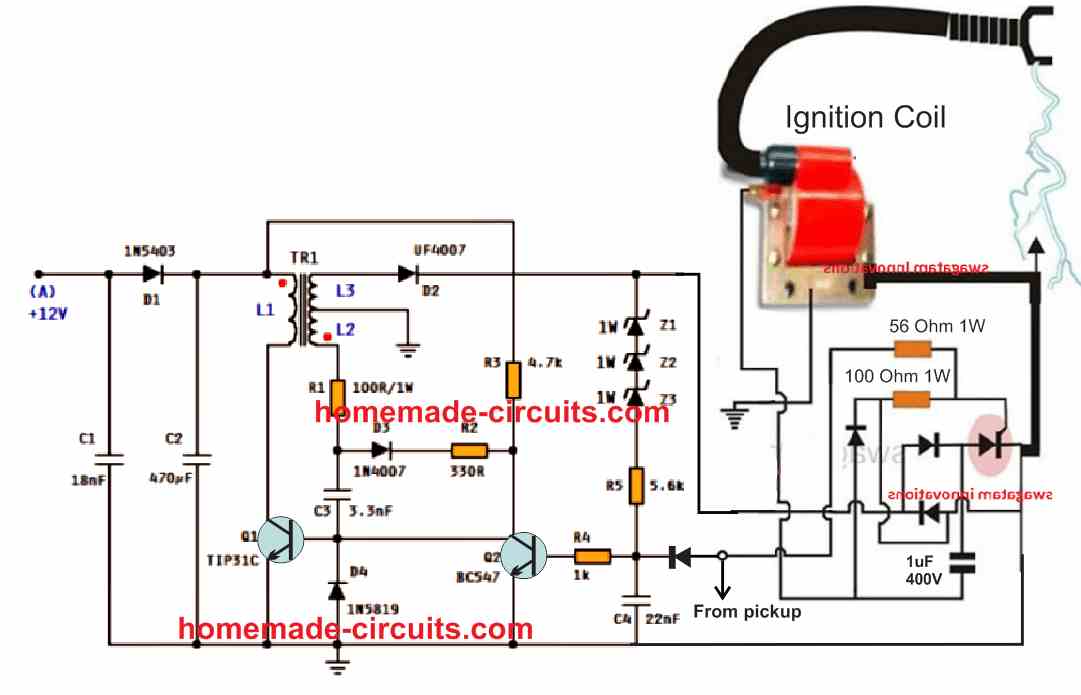
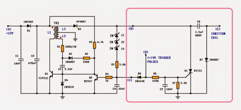
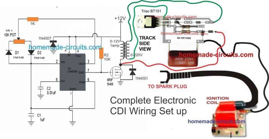
Cdi Unit Circuit Diagram The whole concept for this electronic cdi can be understood by studying the shown circuit diagram below: the diodes, the scr and the associated components form a standard cdi circuit. the high voltage of around 200v which needs to be fed to the above circuit is generated through an ordinary step down transformer connected the other way round. Learn how to connect a 6 pin cdi box to the ignition system of your vehicle using ac or dc power. see illustrated and explained diagrams for different components and wires.

Dc Cdi Circuit Diagram Learn how to wire a dc cdi ignition system for motorcycles and small engines. find out the components, functions, and connections of a dc cdi system and how to interpret the wiring diagram. Simple capacitive discharge ignition (cdi) circuit. Cover this winding with a transformer tape and then start the secondary winding. starting from pin no. 1, wind 140 turns (in the same direction as that for primary) and make a tap at pin no. 2 and then continue another 27 turns and end at pin no. 3. cover the winding with tape and then assemble the 2 ees. it is advisable to make an air gap. Installing a high performance 6 pin dc cdi box but the wiring has you stumped? this video has the diagrams to get your engine running right!read more: https:.

Dc Cdi Schematic Updated Techy At Day Blogger At Noon And A Cover this winding with a transformer tape and then start the secondary winding. starting from pin no. 1, wind 140 turns (in the same direction as that for primary) and make a tap at pin no. 2 and then continue another 27 turns and end at pin no. 3. cover the winding with tape and then assemble the 2 ees. it is advisable to make an air gap. Installing a high performance 6 pin dc cdi box but the wiring has you stumped? this video has the diagrams to get your engine running right!read more: https:. The result is shown in the circuit schematic. because the ignition coil and pickup coil are attached adjacent to the engine’s flywheel, we only need to focus on the electronics that builds the capacitor discharge into a coil at just the right moment. the input is attached to a pickup coil that sends a single pulse for every turn of the flywheel. One crucial component of the motorcycle’s wiring system is the cdi (capacitor discharge ignition) unit, which plays a vital role in ensuring the engine’s smooth operation. understanding the wiring diagram of a dc cdi unit is essential for motorcycle enthusiasts and maintenance personnel.

Wiring Diagram Cdi Dc Wiring Diagram The result is shown in the circuit schematic. because the ignition coil and pickup coil are attached adjacent to the engine’s flywheel, we only need to focus on the electronics that builds the capacitor discharge into a coil at just the right moment. the input is attached to a pickup coil that sends a single pulse for every turn of the flywheel. One crucial component of the motorcycle’s wiring system is the cdi (capacitor discharge ignition) unit, which plays a vital role in ensuring the engine’s smooth operation. understanding the wiring diagram of a dc cdi unit is essential for motorcycle enthusiasts and maintenance personnel.

Electronic 12v Dc Capacitive Discharge Ignition Cdi Circuits

Comments are closed.