Deflection Of Simply Supported Beam With Udl And Point Load The Best Picture

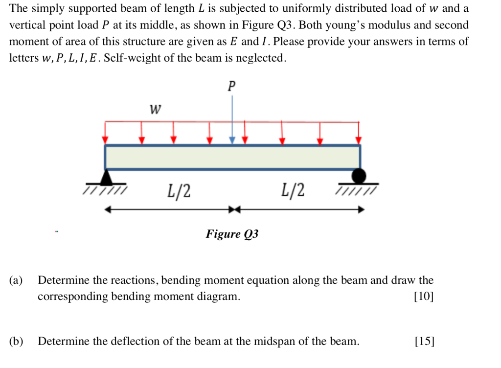
Deflection Of Simply Supported Beam With Udl And Point Loadођ The simply supported beam is one of the most simple structures. it features only two supports, one at each end. a pinned support and a roller support. with this configuration, the beam is allowed to rotate at its two ends but any vertical movement there is inhibited. due to the roller support it is also allowed to expand or contract axially. Beam deflection calculator.

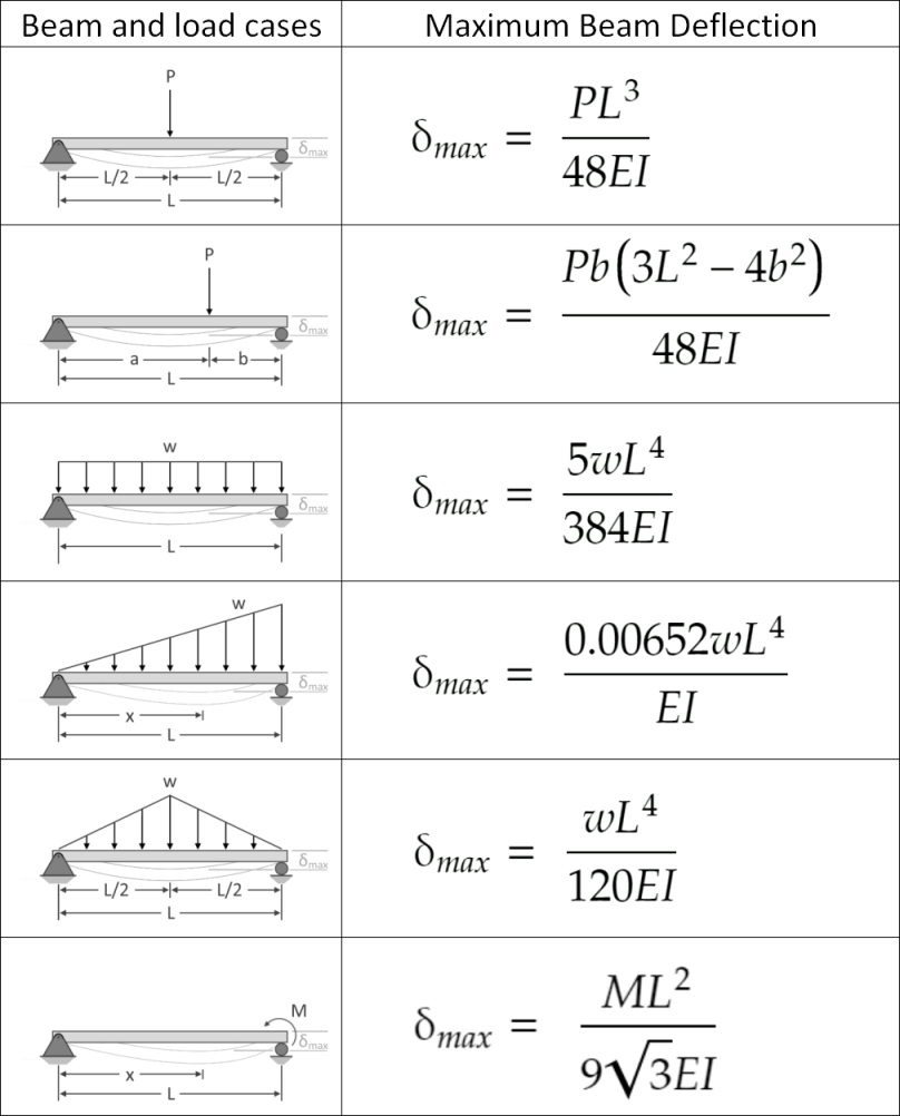
Simply Supported Beam Point Load Deflection Formula The Bestо Simply supported beam calculator. A simply supported beam \(ab\) carries a uniformly distributed load of 2 kips ft over its length and a concentrated load of 10 kips in the middle of its span, as shown in figure 7.3a. using the method of double integration, determine the slope at support \(a\) and the deflection at a midpoint \(c\) of the beam. \(fig. 7.3\). simply supported beam. Simply as x 2 2 d dv mb x ei = exercise 10.1 show that, for the end loaded beam, of length l, simply supported at the left end and at a point l 4 out from there, the tip deflection under the load p is pl3 given by ∆= (316 ⁄ )⋅ ei p a b c l 4 l the first thing we must do is determine the bending moment distribution as a. Bmd = bending moment diagram. e = modulus of elasticity, psi or mpa. i = second moment of area, in 4 or m 4. l = span length under consideration, in or m. m = maximum bending moment, lbf.in or knm. r = reaction load at bearing point, lbf or kn. v = maximum shear force, lbf or kn. w = load per unit length, lbf in or kn m.

Deflection Of Simply Supported Beam With Point Load At Center An Simply as x 2 2 d dv mb x ei = exercise 10.1 show that, for the end loaded beam, of length l, simply supported at the left end and at a point l 4 out from there, the tip deflection under the load p is pl3 given by ∆= (316 ⁄ )⋅ ei p a b c l 4 l the first thing we must do is determine the bending moment distribution as a. Bmd = bending moment diagram. e = modulus of elasticity, psi or mpa. i = second moment of area, in 4 or m 4. l = span length under consideration, in or m. m = maximum bending moment, lbf.in or knm. r = reaction load at bearing point, lbf or kn. v = maximum shear force, lbf or kn. w = load per unit length, lbf in or kn m. Find reactions of simply supported beam when a point load of 1000 kg and a uniform distributed load of 200 kg m is acting on it as shown in figure below. solution. in order to calculate reaction r1, take moment at point c. [latex]\sum m {c}\space = 0[ latex] clockwise moments = anti clock wise moments. r1 x 6 = 1000×3 (200×3)3 2 = 3600. M 1.0 m = 0.3725 kn ⋅ 1.0 m = 0.3725 knm. in dependence of x and the point load q = 0.745kn a general formula for the bending moment of a simply supported beam for 0<x<l 2 can be formulated as: m x = 1 2 ⋅ q ⋅ x. you might have already come across the formula when we set x=l 2.

Comments are closed.