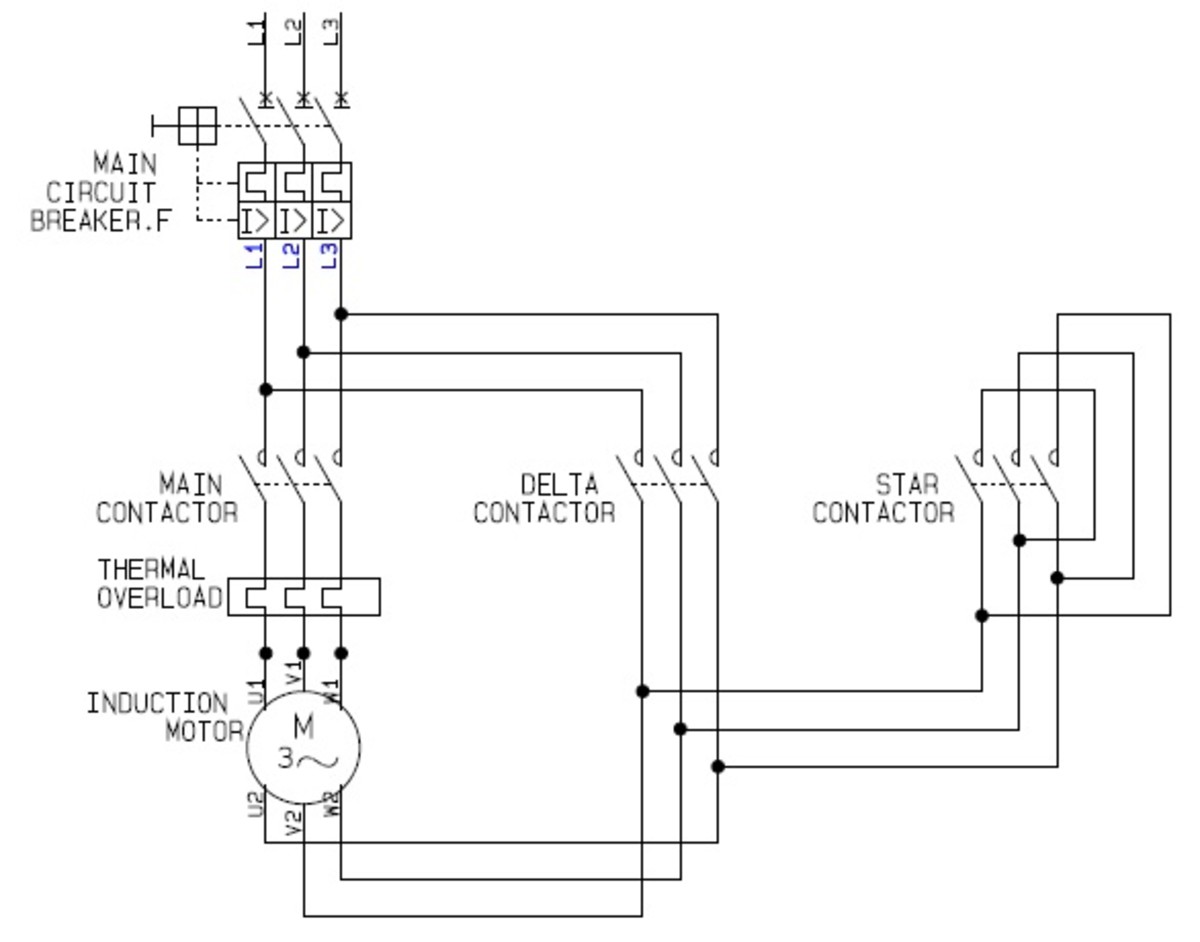
Diagram Electrical Wiring Diagram Schematic Symbols Motor Control

How To Read Motor Control Schematics The control circuit is separate from the motor circuit. the control circuit may not be at the same voltage as the power circuit. when the voltage of the control and power circuits is the same, it is referred to as common control. if the volt ages are different, it is called separate control. figure 4. typical starter wiring diagram — three phase. 19. schematic vs. wiring diagrams. one of the most frequently used diagrams in motor control work is the ladder diagram, also known as a schematic diagram. this diagrams uses symbols to identify components and interconnecting lines to display the electrical continuity of a circuit. ladder diagrams show how a circuit works logically and.

Diagram Electrical Wiring Diagrams Symbols Motor Control Wiring diagrams show the connections to the controller. wiring diagrams, sometimes called “ main ” or “ construction ” diagrams, show the actual connection points for the wires to the components and terminals of the controller. basic wiring for motor control – technical data. they show the relative location of the components. The idea of the electrical or wiring diagram is to trace the flow of power and signals between the sources, control devices, and final loads. these will usually be drawn in a line format from left to right, but are not analogous to ladder diagrams. reading electrical diagrams is one of the most important skills for anyone in a troubleshooting. Required when a two wire control device is used. the bulletin 595 auxiliary contacts are designed as “a” and “b” on the wiring diagram. these contacts are easily. added to any allen bradley bulletin 500 starter sizes 0 through 4. when this system is used, the phase connections on all of the starters must be the same. Decoding a motor control wiring diagram. this table of symbols used in a motor control wiring diagram is intended for electrical technicians and engineers involved in the construction and maintenance of motor starting wiring systems. it offers a thorough understanding of the essential components and symbols found in motor starter wiring schematics.

Comments are closed.