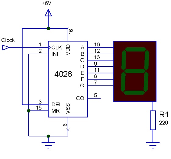
Digital Counter Circuit Diagram

Simple 4026 Manual Digital Counter Circuit With Reset And Pause A counter is a device which stores (and sometimes displays) the number of times a particular event or process has occurred, often in relationship to a clock signal. counters are used in digital electronics for counting purpose, they can count specific event happening in the circuit. for example, in up counter a counter increases count for every. Basic digital counter. may 23, 2024 by electrical4u. 💡. key learnings: digital counter definition: a digital counter is defined as an electronic circuit used to count occurrences of events. flip flops: flip flops, like d and jk types, are the building blocks of digital counters. types of counters: counters can be asynchronous, synchronous.

Digital Counter Circuit Diagram Iot Wiring Diagram Synchronous counters. to avoid the latency inherent in the design of a ripple counter, we need to have all the flip flops update at the same time. that means having them all use the same clock signal. as usual, solving a problem isn't without cost. in this case (indeed in many cases in digital circuit design) this takes the form of more circuitry. As the circuit below. the ic1, ic2 cd4026 (cmos counters decade divider integrated circuit). i like this ic. because they can drive led 7 segment directly. recommended: 0 99 counter using ttl 74ls48, 74ls90. which they connected together. ic1 is a unit counter ic. ic2 is a ten digit counter. and both ics will work at rising edged clock only. A synchronous counter, in contrast to an asynchronous counter, is one whose output bits change state simultaneously, with no ripple. the only way we can build such a counter circuit from j k flip flops is to connect all the clock inputs together, so that each and every flip flop receives the exact same clock pulse at the exact same time:. Counters calculate or note down the number that how many times an event occurred. counters are the crucial hard ware components, and are defined as “the digital circuit which is used to count the number of pulses”. counters are well known to us as “timers”. counter circuits are the best example for the flip flop applications.

A Simple 0 9 Digital Counter Circuit Diagram Etechnog A synchronous counter, in contrast to an asynchronous counter, is one whose output bits change state simultaneously, with no ripple. the only way we can build such a counter circuit from j k flip flops is to connect all the clock inputs together, so that each and every flip flop receives the exact same clock pulse at the exact same time:. Counters calculate or note down the number that how many times an event occurred. counters are the crucial hard ware components, and are defined as “the digital circuit which is used to count the number of pulses”. counters are well known to us as “timers”. counter circuits are the best example for the flip flop applications. A digital circuit which is used for a counting pulses is known counter. counter is the widest application of flip flops. it is a group of flip flops with a clock signal applied. counters are of two types. asynchronous or ripple counters; synchronous counters; asynchronous or ripple counters. the logic diagram of a 2 bit ripple up counter is. Counters, consisting of a number of flip flops, count a stream of pulses applied to the counter’s ck input. the output is a binary value whose value is equal to the number of pulses received at the ck input. each output represents one bit of the output word, which, in 74 series counter ics is usually 4 bits long, and the size of the output.

Comments are closed.