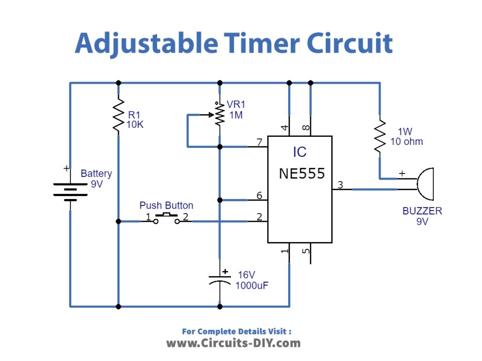
Digital Timer Circuit Diagram

Digital Timer Circuit Using 555 Circuit description. as shown in the diagram, the ic 555 is wired as an astable clock generator circuit. this circuit forms the basic time interval generator stage. the clock pulses are fed to pin 14 of ic2 7490 which is a divide by 10 decade counter, and it divides the clocks from the ic 555 by 10, and the output is generated at its pin11. Digital timer circuit diagram. the following diagram is the schematic diagram of a digital timer and its construction can be done with the help of at89c51 microcontroller, seven segment display, 230v 50hz transformer, bridge rectifier unit, lm7805ct regulator, 12mhz crystal oscillator and buzzer for alarms. these can be arranged as shown in the.

Digital Stop Watch Simple Projects Two step sequential timer. the above circuit can be modified to produce a two step sequential delay generator. this circuit was requested by one of the avid readers of this blog, mr.marco. a simple delay off alarm circuit is shown in the following diagram. the circuit was requested by dmats. the following circuit was requested by fastshack3. A 555 timer can give out only 100 to 200 ma in total. check your chip’s datasheet for the exact value. this pin resets the whole circuit. it’s an “inverted” pin, which means it resets when the pin goes low. this means the pin must be high normally so that the chip isn’t in a “reset” state. Circuit diagram how to adjust and set up. the timer may be adjusted as per the sent request, in the following manner: if we consider the first timing sequence to begin at 7am and end at 12pm, means the upper left timer's p1 needs to be adjusted such that it activates the relay and switches off the relay after exactly 5 hours. Digital clock circuit using ic 555 and 4026 diy electronics projects. lm8560 digital clock circuit diagram with alarm eleccircuit com. clock circuit page 5 meter counter circuits next gr. 1 minute 5 10 and 15 timer circuit diagram using ic 555. simple timer alarm circuit using ic 555. 4541 timer relay circuit 0 3 second to 10 hours. digital.

Programmable Digital Timer Circuit Diagram Circuit diagram how to adjust and set up. the timer may be adjusted as per the sent request, in the following manner: if we consider the first timing sequence to begin at 7am and end at 12pm, means the upper left timer's p1 needs to be adjusted such that it activates the relay and switches off the relay after exactly 5 hours. Digital clock circuit using ic 555 and 4026 diy electronics projects. lm8560 digital clock circuit diagram with alarm eleccircuit com. clock circuit page 5 meter counter circuits next gr. 1 minute 5 10 and 15 timer circuit diagram using ic 555. simple timer alarm circuit using ic 555. 4541 timer relay circuit 0 3 second to 10 hours. digital. Here’s the internal schematics of 555 timer which consists of 25 transistors, 2 diodes and 15 resistors. represented with a block diagram it consists of 2 comparators, a flip flop, a voltage divider, a discharge transistor and an output stage. the voltage divider consists of three identical 5k resistors which create two reference voltages at. For successful circuit building exercises, follow these steps: draw the schematic diagram for the digital circuit to be analyzed. carefully build this circuit on a breadboard or other convenient medium. check the accuracy of the circuit’s construction, following each wire to each connection point, and verifying these elements one by one on.

Digital Timer Circuit Tutorial Here’s the internal schematics of 555 timer which consists of 25 transistors, 2 diodes and 15 resistors. represented with a block diagram it consists of 2 comparators, a flip flop, a voltage divider, a discharge transistor and an output stage. the voltage divider consists of three identical 5k resistors which create two reference voltages at. For successful circuit building exercises, follow these steps: draw the schematic diagram for the digital circuit to be analyzed. carefully build this circuit on a breadboard or other convenient medium. check the accuracy of the circuit’s construction, following each wire to each connection point, and verifying these elements one by one on.

Digital Clock Circuit Using 555 Timer Diagram

Comments are closed.