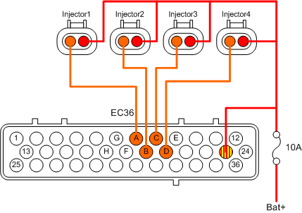
Driver Injector Wiring Diagram

Wiring Staged Injectors Injector driver setup: user configuration the 8 channel fuel injector driver module has user configurable settings that can be adjusted by a set of dip switches concealed behind an access door on the bottom of the enclosure. the dip switches come pre set to position 7 (8a peak 2a hold w long peak duration). Individual injector driver output – to review individual injector driver flow information, review the “injector #1 12 pph” (flow for each injector driver) and “injector #1 12 pw” (pulsewidth for each injector driver). these are found in the data monitor and datalogger views. individual injector set duty cycles would need to be.

Injector Driver Circuit Diagram Injector driver – the injector driver controls the fuel injection timing and provides a signal to the injector to open and close. engine control module (ecm) – the ecm receives signals from the injector driver and controls the operation of the engine. current is supplied to the ecu driver circuits 10 and 20 in example through the fuel. The fuel injector driver circuit schematic pdf offers an easy way to understand all the parts that work together to keep your car running smoothly. it breaks down the wiring diagrams in a comprehensive way, so even if you're new to car maintenance, you can understand what each part is and how they work together. Wiring manual & diagrams 199r10555. The circuit diagram shows the electrical connections and components of the injector driver circuit. it typically includes symbols to represent each component, such as the power supply, control unit, and injector solenoid. the connections between these components are shown using lines and arrows to indicate the flow of electrical current.

Ford 7 3l Injector Drive Module Idm Operation Wiring manual & diagrams 199r10555. The circuit diagram shows the electrical connections and components of the injector driver circuit. it typically includes symbols to represent each component, such as the power supply, control unit, and injector solenoid. the connections between these components are shown using lines and arrows to indicate the flow of electrical current. Peak and hold to the new pro injector driver some fuel map tune will be needed. • idle injection time has to be adjusted. • if necessary, adjust injection time at the entire map. 7. p&h pro injector driver configuration it is easy to configure the p&h pro injector driver using ftmanager software. go to the “external devices” section at. 04 29 2008 12:00 pm. 1999 2003 7.3l power stroke diesel checking a 7.3's idm and injector wiring below the photo is a neat pdf that i ran across. it's a tech bulletin to test an injector driver module (idm) that is produced by the folks that rebuild the electronics in the idms. additionally, for the testing of the wiring for the.

Injector Wiring Diagram Saga Fit Peak and hold to the new pro injector driver some fuel map tune will be needed. • idle injection time has to be adjusted. • if necessary, adjust injection time at the entire map. 7. p&h pro injector driver configuration it is easy to configure the p&h pro injector driver using ftmanager software. go to the “external devices” section at. 04 29 2008 12:00 pm. 1999 2003 7.3l power stroke diesel checking a 7.3's idm and injector wiring below the photo is a neat pdf that i ran across. it's a tech bulletin to test an injector driver module (idm) that is produced by the folks that rebuild the electronics in the idms. additionally, for the testing of the wiring for the.

Comments are closed.