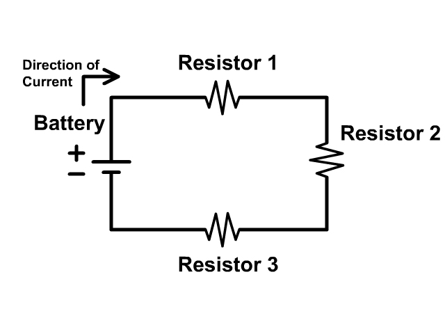
Electric Circuit Diagram With Resistor

Electric Circuit Diagram With Resistor Resistor values in ohms are usually shown as an adjacent number, and if several resistors are present in a circuit, they will be labeled with a unique identifier number such as r 1, r 2, r 3, etc. as you can see, resistor symbols can be shown either horizontally or vertically: real resistors look nothing like the zig zag symbol. An electrical schematic is a diagram that shows how all of the wires and components in an electronic circuit are connected. they’re like a map for building or troubleshooting circuits, and can tell you almost everything you need to know to understand how a circuit works. the ability to read electrical schematics is a really useful skill to.

Circuit Diagram With Resistors This physics video tutorial explains how to read a schematic diagram by knowing what each electric symbol represent in a typical electrical circuit. it cove. Trimmer resistor: preset resistor: thermistor: thermal resistor change resistance when temperature changes: photoresistor light dependent resistor (ldr) photo resistor change resistance with light intensity change: capacitor symbols; capacitor: capacitor is used to store electric charge. it acts as short circuit with ac and open circuit. 1. use circuit symbols to construct schematic diagrams for the following circuits: a. a single cell, light bulb and switch are placed together in a circuit such that the switch can be opened and closed to turn the light bulb on. see answer. b. a three pack of d cells is placed in a circuit to power a flashlight bulb. Basic electrical and electronic graphical symbols called schematic symbols are commonly used within circuit diagrams, schematics and computer aided drawing packages to identify the position of individual components and elements within a circuit. graphical symbols not only identify a components position but the type of electrical element too.

Schematic Diagram Of A Resistor 1. use circuit symbols to construct schematic diagrams for the following circuits: a. a single cell, light bulb and switch are placed together in a circuit such that the switch can be opened and closed to turn the light bulb on. see answer. b. a three pack of d cells is placed in a circuit to power a flashlight bulb. Basic electrical and electronic graphical symbols called schematic symbols are commonly used within circuit diagrams, schematics and computer aided drawing packages to identify the position of individual components and elements within a circuit. graphical symbols not only identify a components position but the type of electrical element too. Resistor definition: a resistor is defined as a two terminal passive electrical element that provides electrical resistance to current flow. primary function: resistors limit and regulate current flow in electrical and electronic circuits. measurement unit: resistance is measured in ohms (Ω), which can be converted to milliohms, kiloohms, and. Parallel circuit: an electric circuit providing more than one conducting path. resistor: a device used to control current in an electric circuit by providing resistance. series circuit: an electric circuit providing a single conducting path such that current passes through each element in turn without branching.

The Following Diagram Shows Resistors In A Circuit Resistor definition: a resistor is defined as a two terminal passive electrical element that provides electrical resistance to current flow. primary function: resistors limit and regulate current flow in electrical and electronic circuits. measurement unit: resistance is measured in ohms (Ω), which can be converted to milliohms, kiloohms, and. Parallel circuit: an electric circuit providing more than one conducting path. resistor: a device used to control current in an electric circuit by providing resistance. series circuit: an electric circuit providing a single conducting path such that current passes through each element in turn without branching.

Comments are closed.