Electrical Wiring Diagram Evinrude Outboard Motor

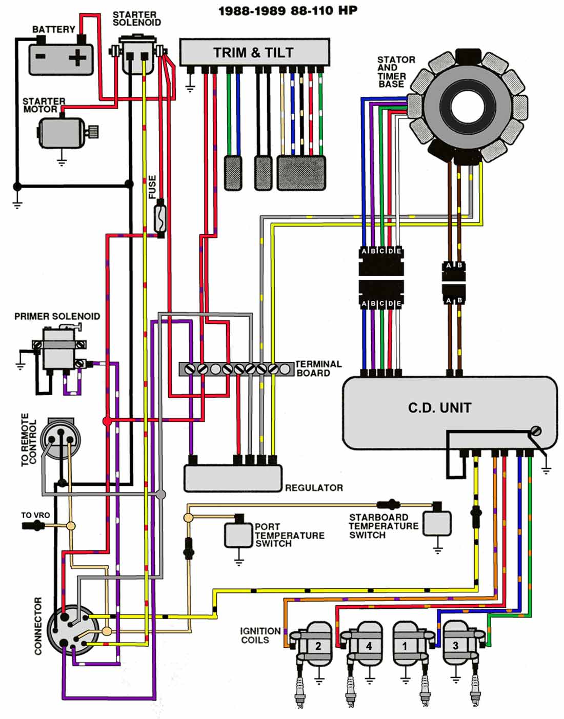
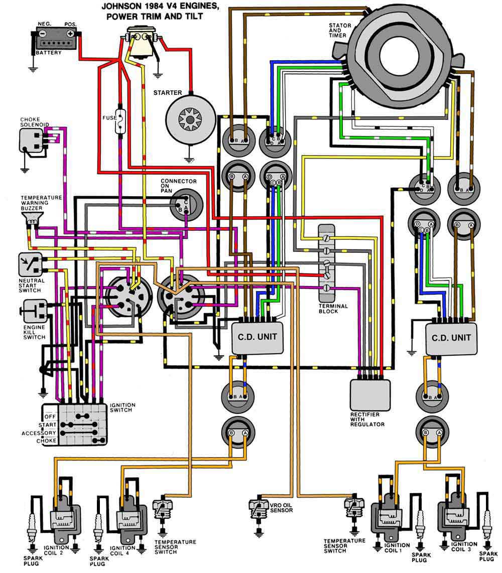
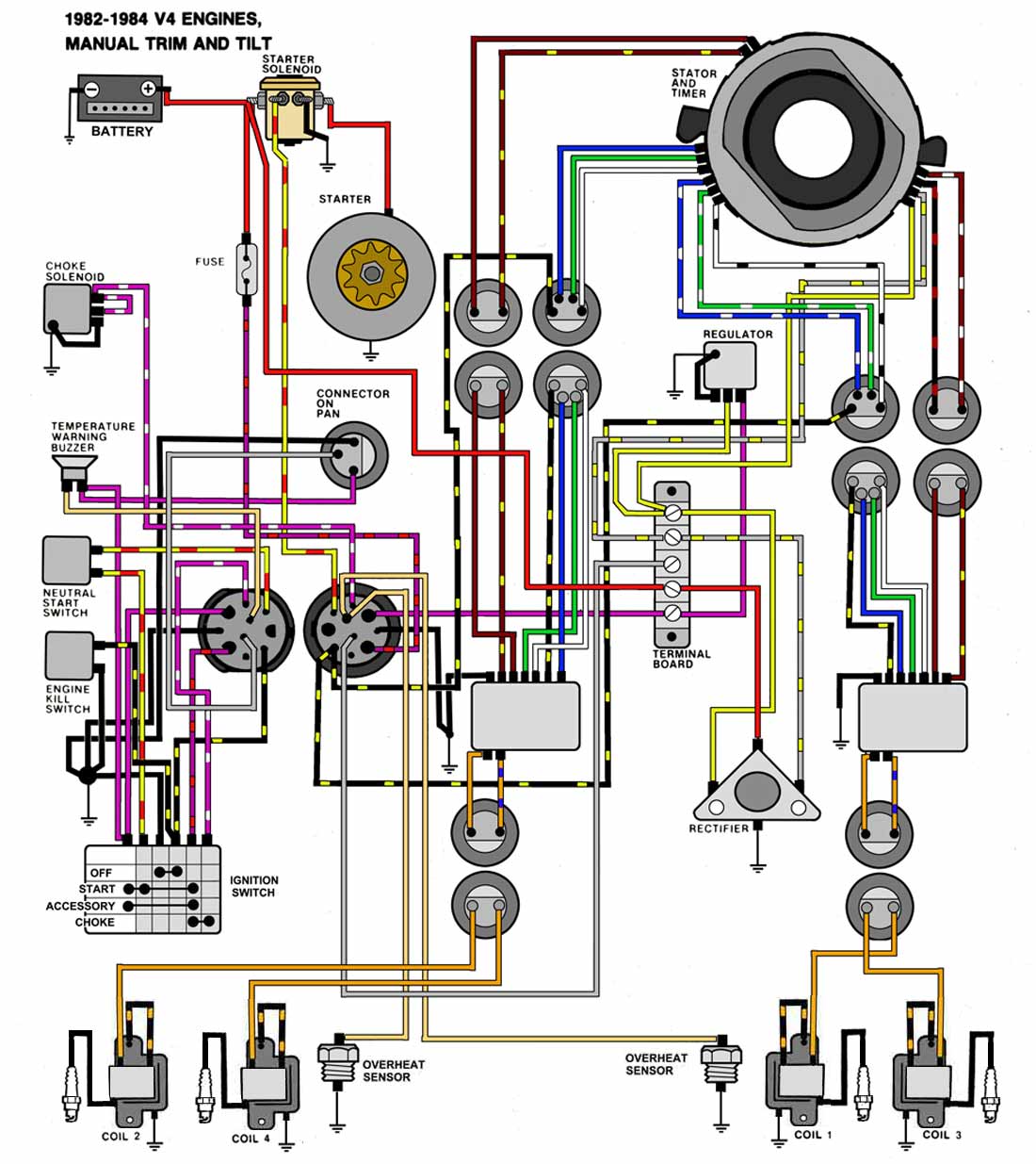
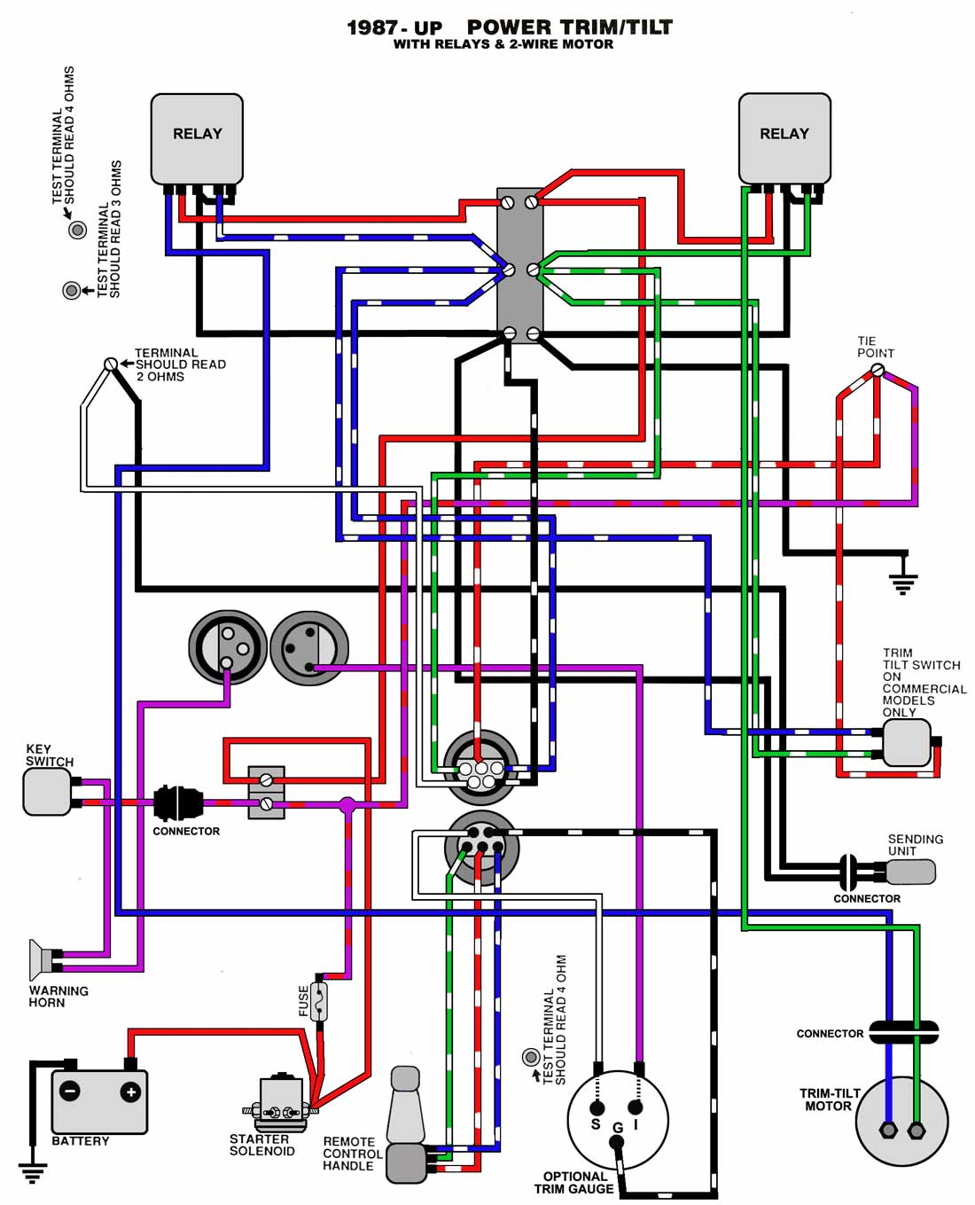
Electrical Wiring Diagram Evinrude Outboard Motor Evinrude wiring diagrams provide a visual representation of the electrical connections and components in your outboard motor, allowing you to diagnose and fix electrical issues easily. whether you’re a seasoned diyer or a boat owner looking to learn more about your motor, this ultimate guide will walk you through everything you need to know. 40 hp electric shift 1967 1968. 40 50 hp with ufi ignition. 55 hp electric shift with alternator 1969. 55 hp 1977 78. 60 70 hp 3 cyl 1978 84. 65 hp 1972 electric shift. 100 & 125 hp 1971 72. v 4 motors 1973 76 cd ignition. v 4 85 hp motors 1969 70 w alternator.

Electrical Wiring Diagram Evinrude Outboard Motor Hey everyone some one put me onto this web site and i found my diagram. so i thought i would share with everyone because i was looking for a diagram for months. this website has johnson evinrude and most other brands, but the link below is just to the omc diagrams. 1st link the wiring diagrams. choose your year and model. Wiring diagrams for outboard motors. new for 2022! we are building up a repository of free wiring diagrams for outboard motor engines for manufacturers such as johnson, evinrude, mariner, mercury, honda, suzuki, tohahsu and more. troubleshoot your outboard starting or ignition system problems with this essential resource. A wiring diagram is a visual representation of the electrical connections and components in your motor, making it easier to understand and follow the wiring process. with a complete guide to wiring your evinrude outboard motor, you can ensure that the electrical system of your motor is set up correctly. one of the key components of a wiring. Gather the necessary tools and materials. before you begin wiring your evinrude ignition system, make sure you have all the tools and materials you need. this includes wire connectors, electrical tape, a wrench or socket set, and the evinrude ignition wiring diagram for your particular model. 2. disconnect the battery.

Electrical Wiring Diagram Evinrude Outboard Motor A wiring diagram is a visual representation of the electrical connections and components in your motor, making it easier to understand and follow the wiring process. with a complete guide to wiring your evinrude outboard motor, you can ensure that the electrical system of your motor is set up correctly. one of the key components of a wiring. Gather the necessary tools and materials. before you begin wiring your evinrude ignition system, make sure you have all the tools and materials you need. this includes wire connectors, electrical tape, a wrench or socket set, and the evinrude ignition wiring diagram for your particular model. 2. disconnect the battery. Check emm led indicators. check wire harness (black yellow) and key stop switch (s). outboard starts and runs, normal performance while running. emm failure. check emm led indicators and eliminate stop circuit as possible cause. stop wire (black yellow) has 4.0 vdc from emm with key on or outboard running. Refer to the engine wiring diagram and the mws instrument wiring diagram in the back of this manual. important: use jumper wires made with the appropriate terminals to test the warning circuits. gauge self test check. turn the key switch to on with the outboard not running.

Electrical Wiring Diagram Evinrude Outboard Motor Check emm led indicators. check wire harness (black yellow) and key stop switch (s). outboard starts and runs, normal performance while running. emm failure. check emm led indicators and eliminate stop circuit as possible cause. stop wire (black yellow) has 4.0 vdc from emm with key on or outboard running. Refer to the engine wiring diagram and the mws instrument wiring diagram in the back of this manual. important: use jumper wires made with the appropriate terminals to test the warning circuits. gauge self test check. turn the key switch to on with the outboard not running.

Comments are closed.