Examples On How To Interpret Gd T Form Orientation Location And Run

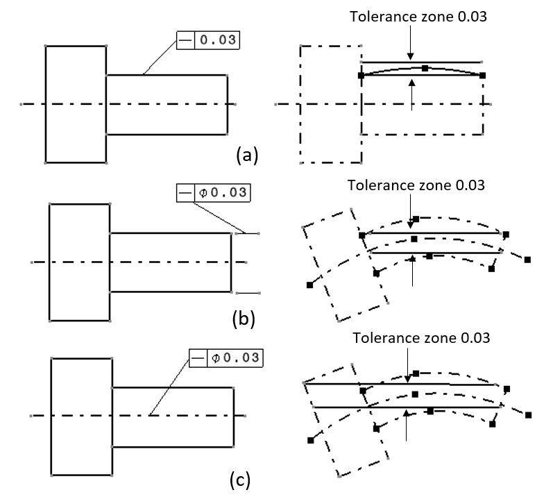
Examples On How To Interpret Gd T Form Orientation Location And Run Figure 1: example of the squareness of an axis line with regards to the axis of a datum. (left) the technical drawing and (right) the gd&t interpretation. the reading and interpretation of the example in figure 1 above is as follow. the axis of the pointed vertical hole should lie within its tolerance zone. Lecture 04defining geometric tolerance (gd&t) controls:form controls:straightness, flatness, circularity, cylindricityorientation controls:angularity, perpen.

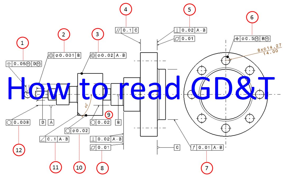
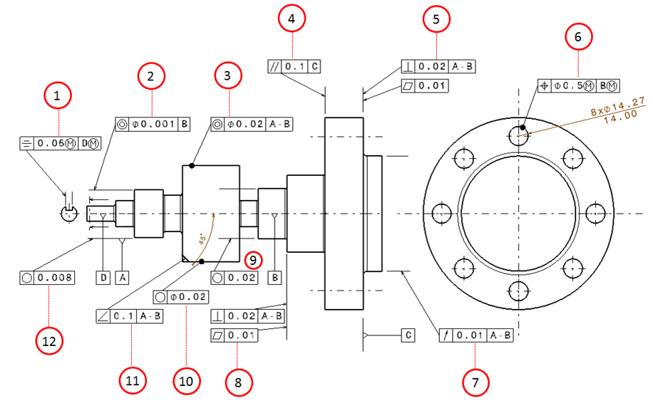
Examples On How To Interpret Gd T Form Orientation Location And Run Bridging the gap between hand tools and cmms. orientation tolerance determines the orientation for the form in relation to a reference. this section explains the symbols of three geometrical characteristics, i.e. parallelism, perpendicularity, and angularity, in an easy to understand manner, using sample drawing indications. Total runout is a composite tolerance that controls the location, orientation and cylindricity of the entire surface simultaneously. it does so by specifying a datum axis and rotating the part by 360 degrees. any peaks and valleys on the surface are observed with respect to the applied total runout tolerance zone. This section explains the four types of geometric tolerances: form tolerance, orientation tolerance, location tolerance, and run out tolerance. it also provides an overview of the maximum material requirement, which is essential to designing the mating of shafts and bores, and the least material requirement, which is effective in designing the thickness of pipes and other parts where. Asme y14.5 is an established, widely used gd&t standard containing all the necessary information for a comprehensive gd&t system. the asme y14.5 standard establishes symbols, definitions, and rules for geometric dimensioning and tolerancing. the purpose of the standard is to ensure clear communication of detailed information throughout the.

Examples On How To Interpret Gd T Form Orientation Location And Run This section explains the four types of geometric tolerances: form tolerance, orientation tolerance, location tolerance, and run out tolerance. it also provides an overview of the maximum material requirement, which is essential to designing the mating of shafts and bores, and the least material requirement, which is effective in designing the thickness of pipes and other parts where. Asme y14.5 is an established, widely used gd&t standard containing all the necessary information for a comprehensive gd&t system. the asme y14.5 standard establishes symbols, definitions, and rules for geometric dimensioning and tolerancing. the purpose of the standard is to ensure clear communication of detailed information throughout the. These standards define the symbols, rules and best practices for using and interpreting gd&t. the latest edition is asme’s y14.5 – 2018. according to the asme, the five categories of gd&t symbols are: form controls. profile controls. orientation controls. location controls. Profile of a line control tolerance in gd&t is a type of profile control tolerance, that controls the size, orientation, location and form of a feature simultaneously. when applied to a surface it creates a 2 dimensional bilateral tolerance zone of two parallel curves around the true surface or feature profile to be controlled. .

Comments are closed.