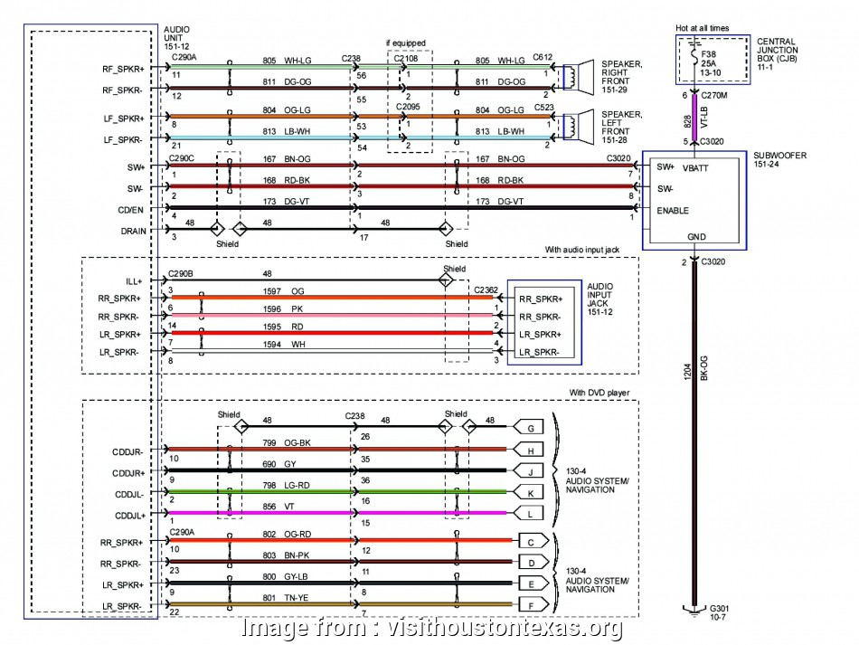
Fabulous 3 Phase 460 Volt Motor Wiring 2007 F150 Trailer Brake Diagram

Fabulous 3 Phase 460 Volt Motor Wiring 2007 F150 Trailer Brake Diagram The three main components of a 3 phase wiring diagram for motors are: power supply: the diagram shows the three phase power supply, typically labeled as l1, l2, and l3. these represent the three separate phases of the power source. motor: the diagram illustrates the motor as a single unit with labeled terminals. 460 volt 3 phase wiring refers to the electrical wiring used for a 3 phase power system that operates at 460 volts. this type of wiring is commonly used in industrial and commercial settings where large amounts of power are required. a 3 phase power system consists of three separate power sources that are out of phase with each other by 120.

2007 F150 Trailer Brake Wiring Diagram Wiring Diagramођ Bg or bge brake rectifier. motor wired for high voltage. brake voltage matches high motor voltage. example: 220 380v motor motor wired 380v brake voltage 380v. the bg brake rectifier standard for frame sizes up to 100, not available on frame sizes above 100. the brake rectifier bg is a half wave rectifier with overvoltage protection. Wiring a 9 lead 3 phase motor involves correctly connecting the nine leads to the corresponding terminals in the motor’s control box. this process requires careful attention to detail and adherence to the manufacturer’s wiring diagram. it is crucial to ensure the correct connection is made to avoid damaging the motor or causing it to. To wire a 3 phase motor, first, identify the wires and check the wiring diagram on the motor. 6 wires are from the motor, 1 for grounding if provided, and 3 (l1 3) from the power supply. choose one of the two configurations (star or delta) and connect the wires to the terminals accordingly. then, connect the ground wire to the grounding. The original wiring diagram showed the proper arrangement of windings to create a larger wye system in which there are four equal windings between any two leads. figure 3. the connections required for high voltage wiring of a wye wound motor. in this wiring setup, there are 4 windings in series between any two line leads.

Step By Step Guide Wiring Diagram For 2007 F150 Trailer Brake To wire a 3 phase motor, first, identify the wires and check the wiring diagram on the motor. 6 wires are from the motor, 1 for grounding if provided, and 3 (l1 3) from the power supply. choose one of the two configurations (star or delta) and connect the wires to the terminals accordingly. then, connect the ground wire to the grounding. The original wiring diagram showed the proper arrangement of windings to create a larger wye system in which there are four equal windings between any two leads. figure 3. the connections required for high voltage wiring of a wye wound motor. in this wiring setup, there are 4 windings in series between any two line leads. Step 3: connect the motor’s terminals. using the wiring diagram as a guide, identify the motor’s terminals and connect them appropriately. this typically involves connecting the three phase wires to the motor’s three terminals, following the diagram’s instructions for proper placement. According to nema, 460v three phase is a “utilization voltage”, while 480v is a “distribution voltage”. simply put, 480v is what the power source supplies, but the equipment within the system is designed to operate at 460v due to power losses. although the drop in the voltage may not be exactly 20v, it will be within that range.

Step By Step Guide Wiring Diagram For 2007 F150 Trailer Brake Step 3: connect the motor’s terminals. using the wiring diagram as a guide, identify the motor’s terminals and connect them appropriately. this typically involves connecting the three phase wires to the motor’s three terminals, following the diagram’s instructions for proper placement. According to nema, 460v three phase is a “utilization voltage”, while 480v is a “distribution voltage”. simply put, 480v is what the power source supplies, but the equipment within the system is designed to operate at 460v due to power losses. although the drop in the voltage may not be exactly 20v, it will be within that range.

Step By Step Guide Wiring Diagram For 2007 F150 Trailer Brake

Comments are closed.