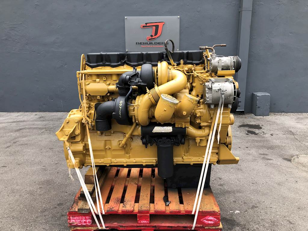
Flow Diagram Cat C15 Cooling System Diagram

Understanding The Coolant Flow In A Cat C15 A Comprehensive Diagram The coolant flow diagram of the cat c15 also includes various components, such as the expansion tank, which provides additional coolant volume and acts as a reservoir for any excess coolant. another important component is the coolant filter, which helps remove contaminants from the coolant, preventing damage to the engine’s cooling system. The vent line is used to release the pressure in the cooling system as the cooling system heats up to operating temperature. this will purge any air out of the system. the oem may supply a surge tank. the tank can be mounted on the radiator or mounted on a remote location. the coolant that expands past the radiator cap is retained in the surge.

C 15 And C 16 Industrial Engines вђ Cooling System Caterpillar Engines Key components of the cat c15 cooling system: radiator: cools the engine coolant with the help of the fan. fan: draws air through the radiator to cool the coolant. water pump: circulates the coolant through the cooling system. thermostat: regulates the flow of coolant to maintain the engine temperature. The cat c15 engine is a powerful and reliable diesel engine used in a variety of applications, including heavy duty trucks, construction equipment, and power generation. it is known for its excellent performance, durability, and fuel efficiency. to understand how the engine works, it is essential to familiarize yourself with its key components. This document describes the cooling system of a c15 or c18 industrial engine. it has a pressurized cooling system with a shunt line that prevents cavitation. the cooling system uses a coolant mixture of 30% ethylene glycol to maintain efficient performance. it explains how the coolant flows through the water pump, oil cooler, cylinder block, cylinder head, and is regulated by the water. This document summarizes the cooling system of a c15 generator set engine. it has a pressure type cooling system with a shunt line to prevent cavitation and allow the system to operate safely above the boiling point of water. a 30% ethylene glycol mixture is used as coolant. the system uses a water temperature regulator and radiator to maintain.

Cat C15 Cooling System Diagram Headcontrolsystem This document describes the cooling system of a c15 or c18 industrial engine. it has a pressurized cooling system with a shunt line that prevents cavitation. the cooling system uses a coolant mixture of 30% ethylene glycol to maintain efficient performance. it explains how the coolant flows through the water pump, oil cooler, cylinder block, cylinder head, and is regulated by the water. This document summarizes the cooling system of a c15 generator set engine. it has a pressure type cooling system with a shunt line to prevent cavitation and allow the system to operate safely above the boiling point of water. a 30% ethylene glycol mixture is used as coolant. the system uses a water temperature regulator and radiator to maintain. Coolant then goes through the core of the radiator to the radiator bottom tank (11) or radiator right side tank (11), where it is again sent through the cooling system. a small amount of coolant goes through inside bypass (10) when temperature regulators (20) are open. note: the water temperature regulators (20) are an important part of the. Tss em0288 02 vs ind 8278180.pdf. diesel engines — up to 7.1 liter all rating conditions are based on iso tr14396, inlet air standard conditions with a total barometric pressure of 100 kpa (29.5 in hg), with a vapor pressure of 1 kpa (.295 in hg), and 25°c (77°f). performance measured using fuel to epa specifications in 40 cfr part 1065 and.

Cat C15 Coolant Flow Diagram Cat Dko Coolant then goes through the core of the radiator to the radiator bottom tank (11) or radiator right side tank (11), where it is again sent through the cooling system. a small amount of coolant goes through inside bypass (10) when temperature regulators (20) are open. note: the water temperature regulators (20) are an important part of the. Tss em0288 02 vs ind 8278180.pdf. diesel engines — up to 7.1 liter all rating conditions are based on iso tr14396, inlet air standard conditions with a total barometric pressure of 100 kpa (29.5 in hg), with a vapor pressure of 1 kpa (.295 in hg), and 25°c (77°f). performance measured using fuel to epa specifications in 40 cfr part 1065 and.

Understanding The Coolant Flow In A Cat C15 A Comprehensive Diagram

Comments are closed.