Ford 4 Wire Alternator Wiring Diagram

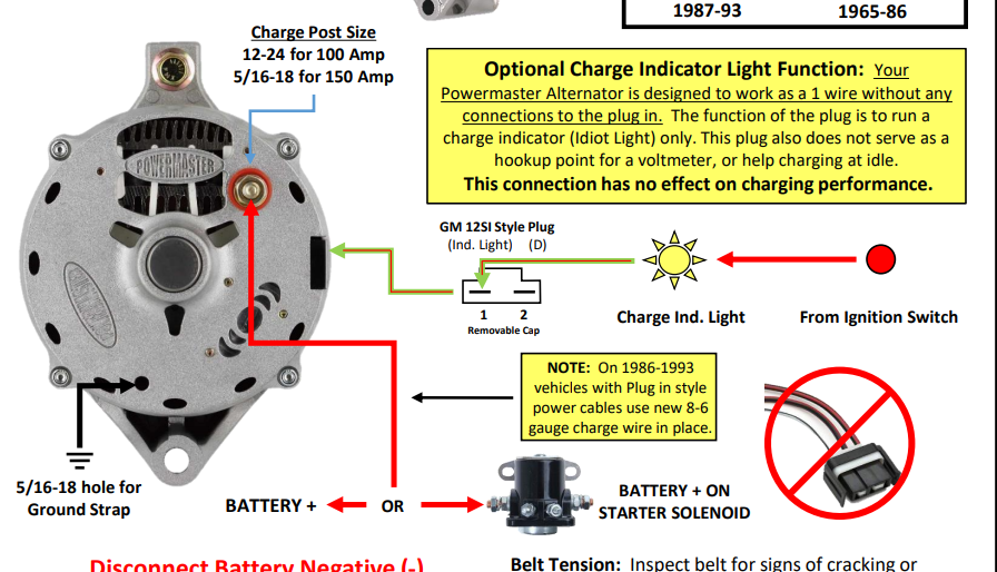
Ford 4 Wire Alternator Wiring Diagram A ford 4 wire alternator diagram is a visual representation of the electrical connections and wiring configuration of a ford alternator with four wires. the diagram illustrates how each wire is connected to the various components, such as the battery, voltage regulator, and charging system. The large output stud of the alternator should be marked b or something similar. this goes to two places one heavy gauge wire with a fusible link goes to the battery side of the solenoid; another wire goes to the a terminal of the voltage regulator. the latter is the sense input to the regulator.

Ford 4 Wire Alternator Wiring Diagram What are the 4 wires on an alternator. an alternator has four wires: the main positive wire, the primary negative wire, the sense wire, and the field wire. these wires provide power to the alternator and help regulate its output. the functions of these wires are as below. Remove the existing alternator and its wiring from the vehicle. locate the three pins on the back of the ford 4g alternator. these pins are labeled “s,” “i,” and “a.”. connect the “s” pin to the vehicle’s ignition switch. this wire provides the necessary voltage to excite the alternator and start the charging process. Prepare for the upgrade: disconnect the battery (negative terminal first), then remove the old alternator and the electrical harness running from the back of the old alternator to the external. 4 wire alternator wiring diagram is the linchpin of a vehicle’s electrical system, seamlessly connecting components from the gm to delco. it ensures an efficient conversion of alternating current from the alternator to direct current for your battery, harmonizing the electrical demands of any car, whether ford or chevrolet.

Comments are closed.