Fuel System Car Anatomy In Diagram

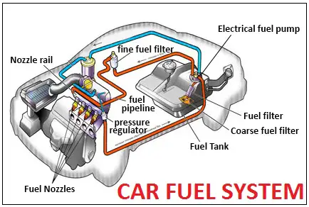
Car Fuel System Block Diagram Diesel Fuel system: components, working principles. A typical car fuel system diagram includes several key components, such as the fuel tank, fuel pump, fuel filter, fuel injectors, and fuel pressure regulator. the fuel tank stores the gasoline or diesel fuel, which is then pumped through the fuel lines by the fuel pump. the fuel filter helps remove impurities and contaminants before the fuel.

Fuel System Car Anatomy In Diagram Fuel pump – is a device which pumping the fuel from tank to the engine; fuel pump of modern injection systems creates enough high pressure. electrical fuel pumps are common using on the modern car. diesel engine pumps can be two types of: low and high pressure. typically high pressure pump are used on the diesel engine. fuel filter (or filters). The ultimate auto fuel system diagram: a comprehensive guide. understanding the workings of a car’s fuel system is essential for any car owner or enthusiast. the fuel system is responsible for delivering fuel to the engine and ensuring it operates smoothly and efficiently. by understanding the different components and their functions within. Fuel system parts diagram. the fuel system is an essential part of any vehicle, as it is responsible for delivering fuel to the engine for combustion. a fuel system typically consists of several components that work together to ensure the efficient and safe delivery of fuel from the fuel tank to the engine. A fuel system schematic diagram is a visual representation of the various components and connections that make up a fuel system in a vehicle, such as a car or a motorcycle. it provides a detailed overview of how fuel is stored, transferred, and utilized in the engine to power the vehicle. at the heart of the fuel system is the fuel tank, which.

Fuel System Car Anatomy In Diagram Fuel system parts diagram. the fuel system is an essential part of any vehicle, as it is responsible for delivering fuel to the engine for combustion. a fuel system typically consists of several components that work together to ensure the efficient and safe delivery of fuel from the fuel tank to the engine. A fuel system schematic diagram is a visual representation of the various components and connections that make up a fuel system in a vehicle, such as a car or a motorcycle. it provides a detailed overview of how fuel is stored, transferred, and utilized in the engine to power the vehicle. at the heart of the fuel system is the fuel tank, which. Simple carburetor diagram: intake system diagram with the simplest carburetor; 1 – pipeline; 2 – hole in the float chamber; 3 – diffuser; 4 – spray; 5 – throttle valve; 6 – mixing chamber; 7 – nozzle; 8 – float chamber; 9 – float; 10 – needle valve; y – simple carburetor, x – ideal carburetor. a nozzle is a metal plug. This is a typical high performance fuel system designed for a 400 to 500hp car. the addition of a mechanical pump is optional if the electric pump is of sufficient capacity. many hot rodders.

Automotive Car Fuel System Infographic Diagram Mechanics Dynamics Simple carburetor diagram: intake system diagram with the simplest carburetor; 1 – pipeline; 2 – hole in the float chamber; 3 – diffuser; 4 – spray; 5 – throttle valve; 6 – mixing chamber; 7 – nozzle; 8 – float chamber; 9 – float; 10 – needle valve; y – simple carburetor, x – ideal carburetor. a nozzle is a metal plug. This is a typical high performance fuel system designed for a 400 to 500hp car. the addition of a mechanical pump is optional if the electric pump is of sufficient capacity. many hot rodders.

Comments are closed.