Gm Ignition Control Module Wiring Diagram

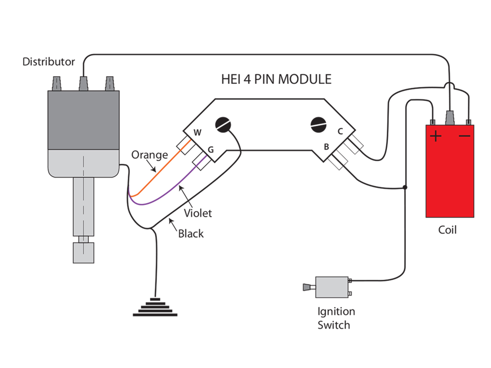
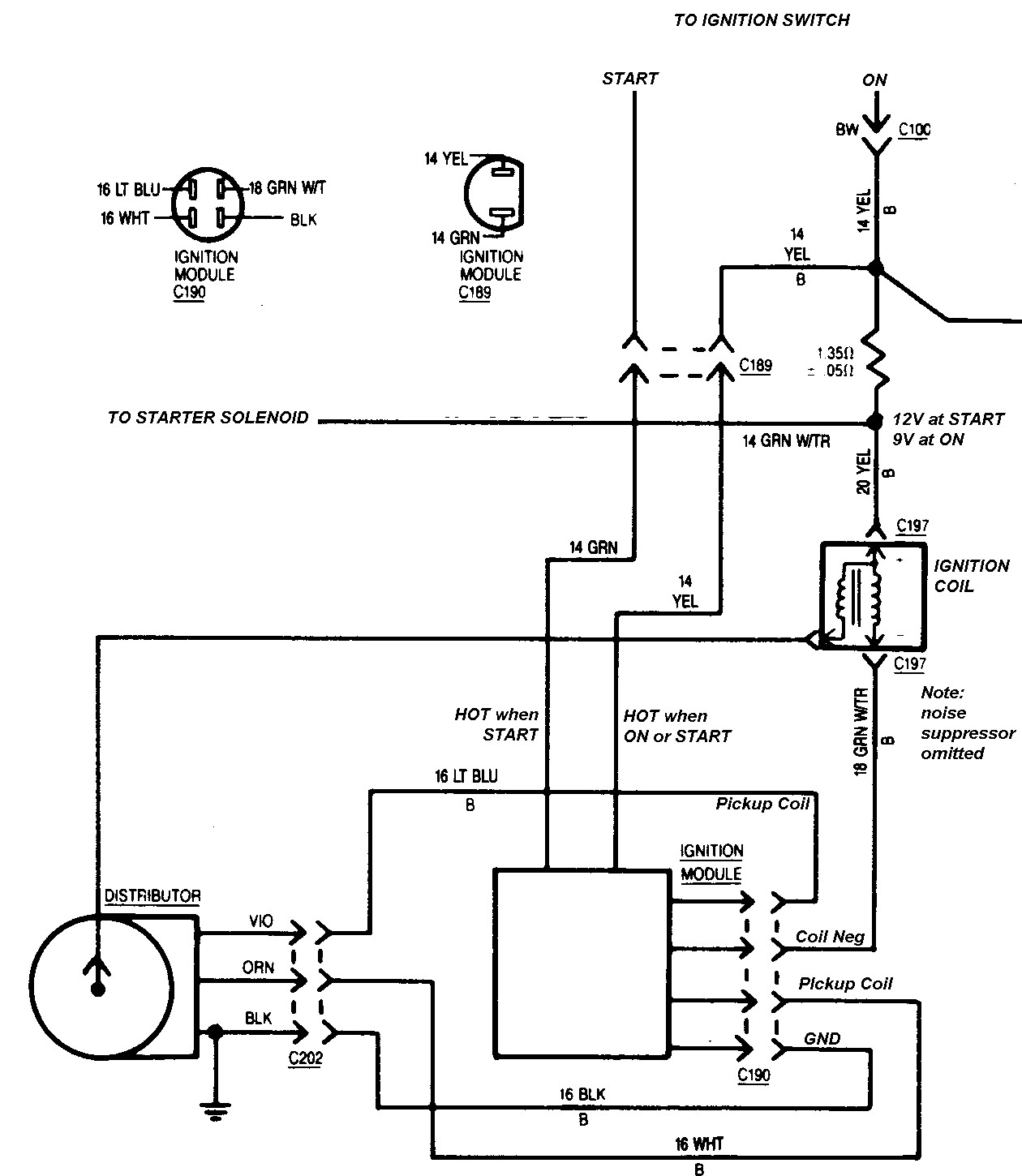
Ford Ignition Control Module Wiring Diagram Wiring Diagram In addition to the ignition switch connection, the gm hei module wiring diagram also includes the connections to the distributor and coil. these connections allow the module to control the timing and firing of the spark plugs. by following the wiring diagram, technicians can ensure that these connections are properly made, preventing misfires. Ignition control module (icm) circuit descriptions. the ignition control module (icm) has 4 wires coming out of it. below are the descriptions of what each circuit does. each circuit is identified by a letter, and this is the same letter that you will find on the ignition module's connector. circuit labeled a pink wire: power (12 v) circuit.

Ford Ignition Control Module Wiring Diagram Cadician S Blog The typical ignition system circuit diagram for the 1996 1999 4.3l, 5.0l, and 5.7l 1500, 2500, 3500 pick up and suburban can be found here: ignition system circuit diagram (1996 1999 chevy gmc pick up and suv). ignition system diagnostic manual download. testing a no start problem or a misfire due to an ignition system problem is not hard. When you find a suitable location to mount the unit, make sure the wires of the ignition reach their connections. hold the ignition in place and mark the location of the mounting holes. use an 1 8" drill bit to drill the holes. use the supplied self tapping screws to mount the box. This tutorial will help you test the ignition coil, ignition module, and the crankshaft position sensor: how to test the gm ignition control module (1995 2005). the typical ignition system circuit diagram for the 1992 1995 4.3l, 5.0l, and 5.7l 1500, 2500, 3500 pick up and suburban can be found here: ignition system circuit diagram (1992 1995. Gm’s high energy ignition (hei) distributor has been used as an affordable, easy to install performance distributor since its introduction in the mid 70s. it should come as no surprise being one of the most popular options among modern rodders and race enthusiasts to this day. most of the original gm v 6 and v 8 models used an ignition coil.

Gm Ignition Module Wiring Schematic This tutorial will help you test the ignition coil, ignition module, and the crankshaft position sensor: how to test the gm ignition control module (1995 2005). the typical ignition system circuit diagram for the 1992 1995 4.3l, 5.0l, and 5.7l 1500, 2500, 3500 pick up and suburban can be found here: ignition system circuit diagram (1992 1995. Gm’s high energy ignition (hei) distributor has been used as an affordable, easy to install performance distributor since its introduction in the mid 70s. it should come as no surprise being one of the most popular options among modern rodders and race enthusiasts to this day. most of the original gm v 6 and v 8 models used an ignition coil. Connect the wiring harness. once the ignition module is located, carefully connect the wiring harness to the module. make sure to match the corresponding wire colors and connectors. use wire crimpers and connectors to securely attach the wires. double check all connections to ensure they are tight and secure. The 7 pin hei module. with a gm hei 7 pin (and 8 pin modules), the ignition module wires you need to know about are: tach signal is a purple wire with a white trace [ pin r ] advance control signal is a white wire [ pin e ] override (cranking) signal is a tan wire with a black trace [ pin b ] ground is a black wire with a red trace [grounded to.

Comments are closed.