Ic 555 Delay Timer Circuit Easy Timer Circuit On Off Delay

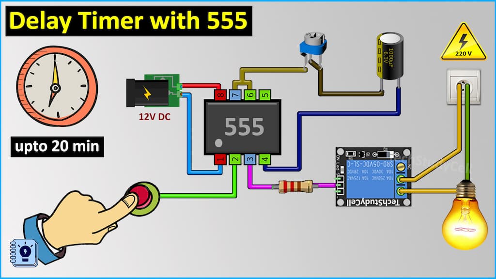
Time Delay Relay Circuit Using 555 Timer Ic Off Delay T Step 1: 555 timer ic in monostable mode. lets start by putting all the components together and lets understand how the circuit works. in the first example, i am going to show you guys the "on off timer circuit" with a fixed timing resistor and capacitor. the heart of this circuit is the 555 timer ic. 1. ne555dr. the 555 timer ic is an integrated circuit (ic) that is used in a variety of timer, delay, pulse generator and oscillator circuits. in this tutorial, i am going to show you guys how to make an "adjustable delay timer circuit" using the 555 timer ic. this circuit can automatically turn on off any circuit after a fixed duration.

555 Timer Ic Types Construction Working Applications 52 Off If the trigger pin (pin 2 of the 555 timer ic) senses any voltage less than 1 3rds of the supply voltage, it turns on the output. if the threshold pin (pin 6 of the 555 timer ic) senses any voltage more than 2 3rds of the supply voltage, it turns off the output. whenever the output of the 555 timer ic is in off state, the discharge pin (pin 7. On delay timer, off delay timer & star delta timer. in today’s tutorial, we are going to go over a step by step process on how to make an on off delay timer circuit using ne555 precision timer ic. 555 timer ic. ne555 is a precision timing circuit capable of producing accurate time delays or oscillation. a ne555 has three basic modes of. A tutorial on how to build an adjustable auto power on off delay timer circuit using 555 timer in monostable mode. this electronic timer circuit is helpful w. In this 555 timer project, i have shown how to make a time delay relay circuit using 555 timer ic to automatically turn off the switch after a predefined delay. you can also adjust the off delay time up to 20 minutes with a 1m pot. in this article, i have shared the required components, complete circuit diagram, pcb layout, and all other.

Ic 555 Delay Timer Circuit Easy Timer Circuit On Off Delay Circuit A tutorial on how to build an adjustable auto power on off delay timer circuit using 555 timer in monostable mode. this electronic timer circuit is helpful w. In this 555 timer project, i have shown how to make a time delay relay circuit using 555 timer ic to automatically turn off the switch after a predefined delay. you can also adjust the off delay time up to 20 minutes with a 1m pot. in this article, i have shared the required components, complete circuit diagram, pcb layout, and all other. Introduction. here we are going to make a simple on off 555 delay timer 555 with the help of 555 timer ic. you can adjust the delay time for both on and off circuits by changing the values of resistors and capacitors. if you want to make this project with us then follow each and every step carefully. also, do check out more projects on 555. The 555 timer delay before turn on circuit we will build is shown below. the breadboard schematic of the above circuit is shown below. to connect power to the 555 timer chip, we connect about 5 15v to v cc, pin 8 and we connect pin 1 to ground. we connect a 100μf capacitor to the positive voltage supply and then to pin 2.

Time Delay Relay Circuit Using 555 Timer Ic Electronics Projects Introduction. here we are going to make a simple on off 555 delay timer 555 with the help of 555 timer ic. you can adjust the delay time for both on and off circuits by changing the values of resistors and capacitors. if you want to make this project with us then follow each and every step carefully. also, do check out more projects on 555. The 555 timer delay before turn on circuit we will build is shown below. the breadboard schematic of the above circuit is shown below. to connect power to the 555 timer chip, we connect about 5 15v to v cc, pin 8 and we connect pin 1 to ground. we connect a 100μf capacitor to the positive voltage supply and then to pin 2.

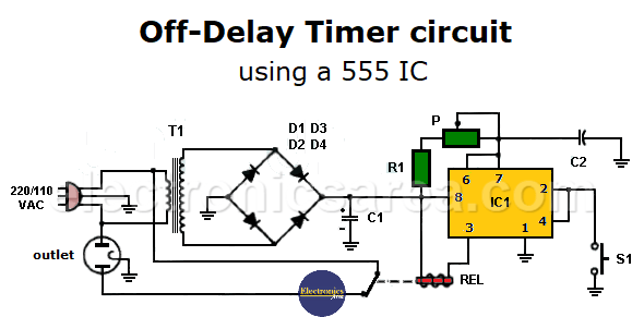
Off Delay Timer Circuit Using 555 Ic Electronics Area

Comments are closed.