Introduction To 555 Timer The Internal Block Diagram And The Pin Diagram Explained

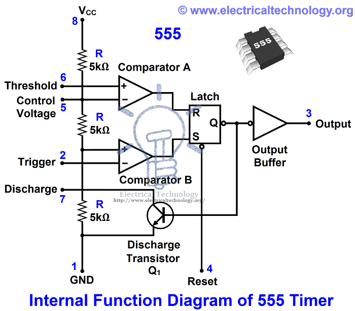
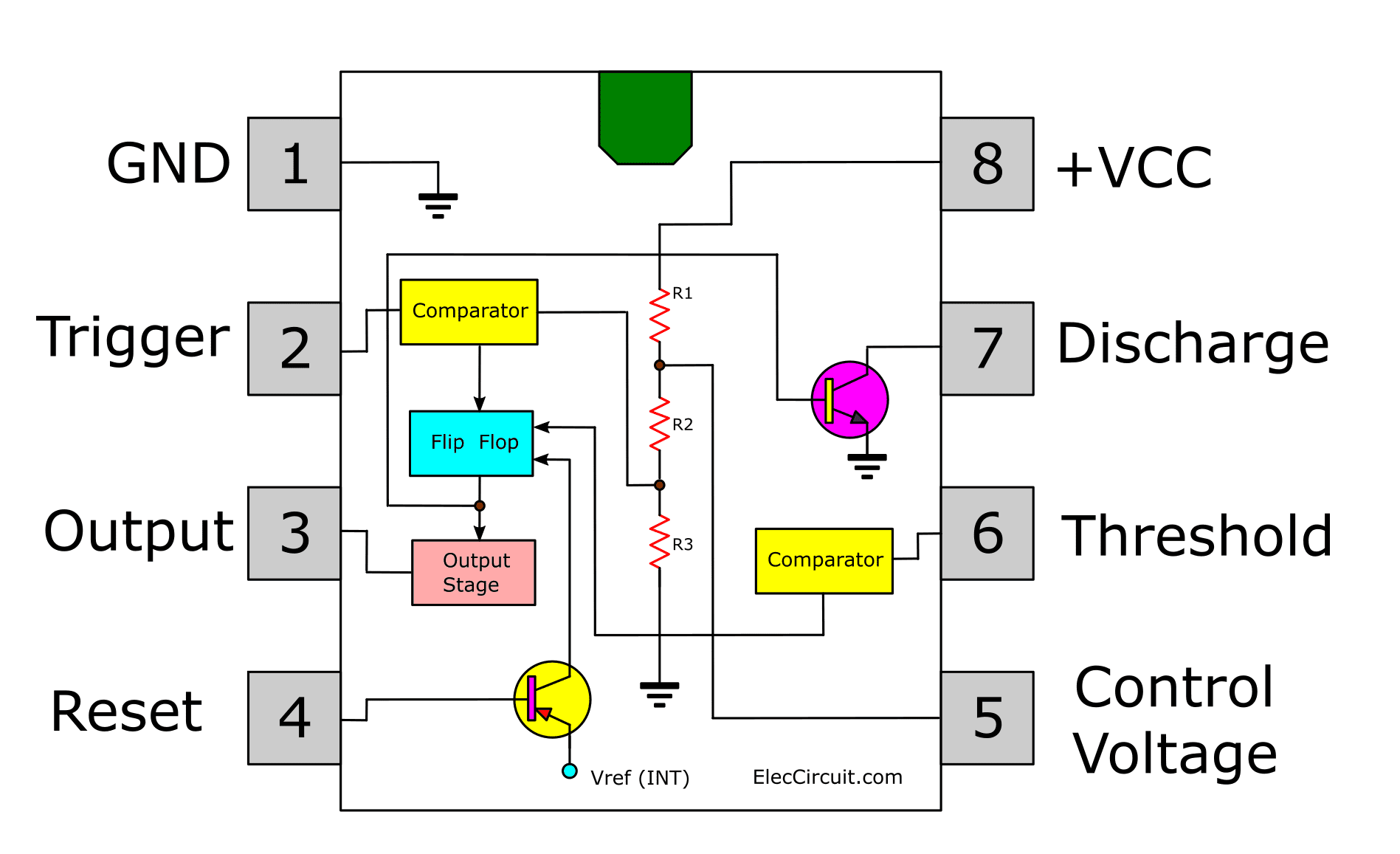
Introduction To 555 Timer The Internal Block Diagram And The In this video, the brief introduction to the 555 timer ic has been given and the pin diagram (of 8 pin dip 555 ic) and the internal block diagram of the 555. Here’s the internal schematics of 555 timer which consists of 25 transistors, 2 diodes and 15 resistors. represented with a block diagram it consists of 2 comparators, a flip flop, a voltage divider, a discharge transistor and an output stage. the voltage divider consists of three identical 5k resistors which create two reference voltages at.

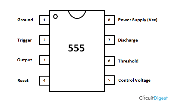
Pin Diagram Of 555 Timer In this video, how the 555 timer works explained, 555 timer ic is one of the most popular and widely used ics of all time.the timestamps of various topics co. The behavior of the 555 timers is controlled by the three input pins: threshold, trigger, and control voltage. when the voltage on the threshold pin increases above the 2 3 v cc reference voltage, we get a logic “1” at the output “a”. otherwise, the output “a” is a logic “0”. figure 3: threshold and trigger comparators. 555 timer pin diagram and descriptions. now as shown in figure, there are eight pins for a 555 timer ic namely, 1.ground. 2.trigger. 3.output. 4.reset. 5.control. 6.threshold. 7.discharge. 8.power or vcc . pin 1. ground: this pin has no special function what so ever. it is connected to ground as usual. The se 555 timer ic works between the temperature range of – 55°c to 125°c in se and the ic ne 555 is used for where the temperature ranges from 0° to 70°c. it has a wide range of usages in the electronic field as a timer, delay, pulse generation, oscillator, etc. you can check the datasheet of ne555 ic if you want to learn more about it.

555 Timer Ic Internal Structure Working Pin Diagram And Description 555 timer pin diagram and descriptions. now as shown in figure, there are eight pins for a 555 timer ic namely, 1.ground. 2.trigger. 3.output. 4.reset. 5.control. 6.threshold. 7.discharge. 8.power or vcc . pin 1. ground: this pin has no special function what so ever. it is connected to ground as usual. The se 555 timer ic works between the temperature range of – 55°c to 125°c in se and the ic ne 555 is used for where the temperature ranges from 0° to 70°c. it has a wide range of usages in the electronic field as a timer, delay, pulse generation, oscillator, etc. you can check the datasheet of ne555 ic if you want to learn more about it. A monostable 555 timer is required to produce a time delay within a circuit. if a 10uf timing capacitor is used, calculate the value of the resistor required to produce a minimum output time delay of 500ms. 500ms is the same as saying 0.5s so by rearranging the formula above, we get the calculated value for the resistor, r as:. Pin 2 of the 555 timer is kept high by resistor r2, but the instant it goes low, the timing period starts, and the output on pin 3 goes high for a period determined by potentiometer r1 and capacitor c3. to calculate the time pin 3 will be high, use this equation: t = 1.1 * r1 * c3. when this period ends, pin 3 goes low again.

Timer 555 Circuit Diagram A monostable 555 timer is required to produce a time delay within a circuit. if a 10uf timing capacitor is used, calculate the value of the resistor required to produce a minimum output time delay of 500ms. 500ms is the same as saying 0.5s so by rearranging the formula above, we get the calculated value for the resistor, r as:. Pin 2 of the 555 timer is kept high by resistor r2, but the instant it goes low, the timing period starts, and the output on pin 3 goes high for a period determined by potentiometer r1 and capacitor c3. to calculate the time pin 3 will be high, use this equation: t = 1.1 * r1 * c3. when this period ends, pin 3 goes low again.

Comments are closed.