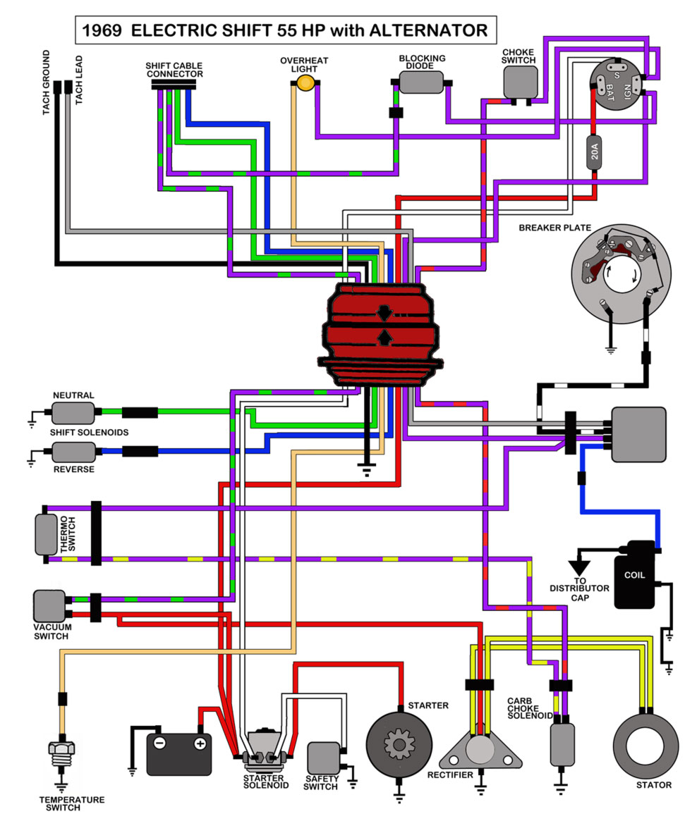
Johnson Outboard Tachometer Wiring

Johnson Outboard Tachometer Wiring Re: wiring tach from johnson controls. the rubber plug you describe is there for the plug in type tachometer it simply plugs in and the tachometer works. on the other side of that plug is a: purple wire: 12v supply for the tachometer. gray wire: sensor lead for the tachometer. black wire: ground lead for the tachometer. When installing a tachometer on your johnson outboard motor, it is essential to correctly identify and connect the wires. understanding the wiring diagram and color coding will help ensure a successful installation. 1. power and ground wires: the tachometer requires a power source and ground connection to function.

Johnson Outboard Tachometer Wiring Diagram How to install a tach. This "how to" video will demonstrate the step by step process of installing a tach hour meter on an outboard marine motor. the tachometer is useful if you. The wiring diagram for a johnson outboard tachometer is relatively straightforward. it typically involves connecting a few wires from the tachometer to specific terminals on the motor. however, it’s crucial to refer to the manufacturer’s instructions or consult a professional to ensure proper installation and avoid damaging the motor. Installation. disconnect battery cables to help prevent arcing or damage to equipment. select a tachometer mounting location that is in full view of the operator. drill a 3 3 8 in. (86mm) hole in the dashboard. mount the tachometer so water will not collect on the face, or drip on the case and wires.

Comments are closed.