Ka3525 Sg3525 Inverter Circuit Diagram Schematic Of Sg3525 Based Push

Sg3525 Schematic This is a simplified inverter circuit using the sg3525a. depending on the specific application, additional components and considerations may be necessary for efficiency, stability, and safety. here is how it will look like after fully assembled on pcb, sg3525 inverter circuit. here are the top and bottom images of pcb without component. In this post i have explained a 3 powerful yet simple sine wave 12v inverter circuits using a single ic sg 3525. the first circuit is equipped with a low battery detection and cut off feature, and an automatic output voltage regulation feature. this circuit was requested by one of the interested readers of this blog.

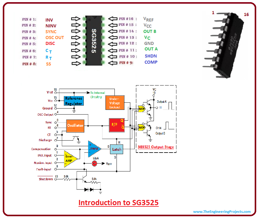
Sg3525 Power Inverter Circuit With Output Voltage Regulation Complete The sg3525 is a popular integrated circuit that is widely used in the design of sinusoidal pulse width modulation (pwm) inverters. the circuit diagram of a pure sine wave inverter using the sg3525 is relatively simple. it consists of an sg3525 chip, a few electrical components such as resistors, capacitors, and diodes, and a power transformer. The following image shows an example inverter circuit using the ic sg3525, you can observe that the output mosfet stage is missing in the diagram, and only the output open pinouts can be seen in the form of pin#11 and pin#14 terminations. the ends of these output pinouts simply needs to be connected across the indicated sections of the above. Circuit link: electrobuff 2024 02 sg3525 power inverter circuit with hi, in today's video i'll show you how to make a regulated power. Overview. in this project, we will make an 300w, 50 60 hz inverter using ic sg3525 with pwm inverter circuit. the circuit will take a 12v dc power supply from a 12v battery and converts it into 220v, 300w pwm output. an inverter is an electronic device that converts direct current (dc) electricity into alternating current (ac) electricity.
Ka3525 Sg3525 Inverter Circuit Diagram Schematic Of S Vrogue Co Circuit link: electrobuff 2024 02 sg3525 power inverter circuit with hi, in today's video i'll show you how to make a regulated power. Overview. in this project, we will make an 300w, 50 60 hz inverter using ic sg3525 with pwm inverter circuit. the circuit will take a 12v dc power supply from a 12v battery and converts it into 220v, 300w pwm output. an inverter is an electronic device that converts direct current (dc) electricity into alternating current (ac) electricity. The topic about using the sg3525 pwm controller explanation and example: circuit diagram schematic of push pull converter is fabulous.it's a good post for me because i am always interesting to know about the inverters,it's shelling and products .thanks sir for this useful post which is very much important for me.thanks again dc power inverter. In this post we learn how to build 3 unique power inverter circuits using the ic sg3525. all these inverters will produce 220 v or 110 v ac from any 12 v automobile lead acid battery. on camping grounds, automobile repairs in the heart of nowhere, and picnics or party gatherings in the woods, the unavailability of a main supply power outlet is.

Comments are closed.