Kubota Rtv 900 Cooling Fan Wiring Diagram

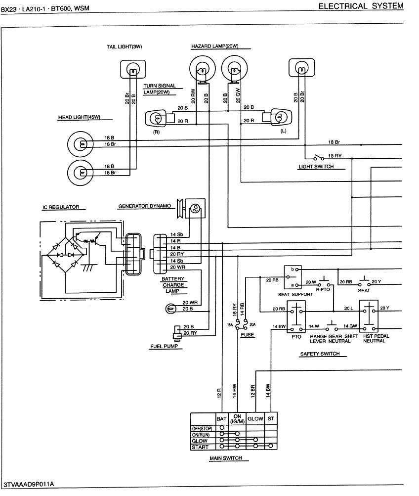
Kubota Rtv 900 Wiring Diagram Pdf Relay hazard switch. blinker switch. coolant temperature switch head light (37.5 w) light switch output (buzzer) brake lamp switch blinker 2 speed meter (if equipped) blinker 1 fan motor 12v dc output. hydraulic lever lamp. hydraulic lever switch flasher unit. turf model only. alternator fuse. Page 100 rtv900, wsm engine fan belt damage and wear 1. check the fan belt for damage. 2. if the fan belt is damaged, replace it. 3. check if the fan belt is worn and sunk in the pulley groove. 4. if the fan belt is nearly worn out and deeply sunk in the pulley groove, replace it.

Kubota Rtv 900 Wiring Diagram Pdf Wiring Diagram Pictures See the fan has power going to it all the time, it's just waiting for the sensor to ground out when the engine starts to overheat. switch on the dash will let you control when it comes on, but the engine sensor should be doing that when working normally. good luck. jul 29, 2023 rtv900 overheating, cooling fan off #8. Kubota rtv900 wiring diagrams may vary depending on the model year. for instance, a wiring diagram for a 2004 model will be completely different from one for a 2020 model. it is important to note, however, that all wiring diagrams follow the same general format. each contains three primary sections—the component layout, the power system and. Rtv900, wsm specifications specifications note: * manufacture’s estimate the company reserves the right to change the specifications without notice. w1028103 model general purpose worksite turf recreational engine maker kubota model d902 e uv d902 e2 uv type indirect injection. vertical, water cooled, 4 cycle diesel number of cylinders 3. Page 27: air cleaner wire harness radiator hose rtv900, wsm new transmission air cleaner, wire harness, radiator hose (upper), cables and brake cylinder 1. remove the air cleaner body and intake hose as a unit. 2. disconnect the wire harness (1) from engine, alternator and stator motor. 3. remove the ground cable (5) and positive cable (4). 4.

Kubota Rtv 900 Wiring Schematic Wiring Diagram Rtv900, wsm specifications specifications note: * manufacture’s estimate the company reserves the right to change the specifications without notice. w1028103 model general purpose worksite turf recreational engine maker kubota model d902 e uv d902 e2 uv type indirect injection. vertical, water cooled, 4 cycle diesel number of cylinders 3. Page 27: air cleaner wire harness radiator hose rtv900, wsm new transmission air cleaner, wire harness, radiator hose (upper), cables and brake cylinder 1. remove the air cleaner body and intake hose as a unit. 2. disconnect the wire harness (1) from engine, alternator and stator motor. 3. remove the ground cable (5) and positive cable (4). 4. As stated above there are 3 things to effect the fan basically.the relay the temp sensor and fuse.when the ignition is on it throws the relay to apply a constant 12 volts to the fan. when the engine heats up do its desired temp the temp sensor switch will activate and apply a ground to the circuit completing the connection to make the fan to. Page 106: cooling system engine rtv x900, rtv x1120d, wsm 3. cooling system the cooling fin is set up around the oil passage in the gear case. therefore, the temperature of oil is decreased by the wind generated by the cooling fan. (1) cooling fin (rtv x900) page 107: fuel system engine rtv x900, rtv x1120d, wsm 4.

пёџkubota Rtv 900 Cooling Fan Wiring Diagram Free Download Goodi As stated above there are 3 things to effect the fan basically.the relay the temp sensor and fuse.when the ignition is on it throws the relay to apply a constant 12 volts to the fan. when the engine heats up do its desired temp the temp sensor switch will activate and apply a ground to the circuit completing the connection to make the fan to. Page 106: cooling system engine rtv x900, rtv x1120d, wsm 3. cooling system the cooling fin is set up around the oil passage in the gear case. therefore, the temperature of oil is decreased by the wind generated by the cooling fan. (1) cooling fin (rtv x900) page 107: fuel system engine rtv x900, rtv x1120d, wsm 4.
Kubota Rtv 900 Wiring Schematic Diagram Board

Comments are closed.