Learn How To Draw Shear Force And Bending Moment Diagrams In 2023

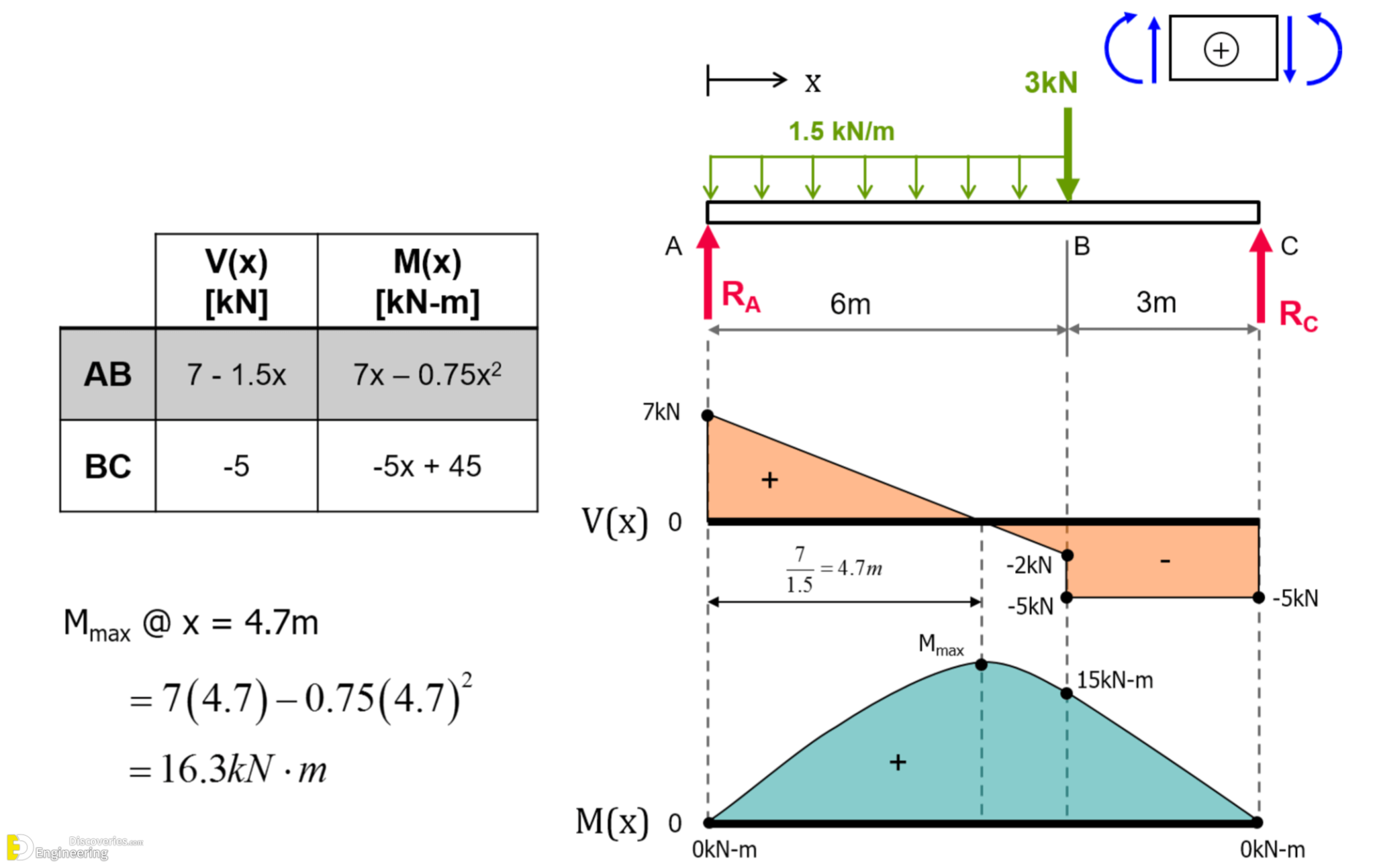
Learn How To Draw Shear Force And Bending Moment Diagrams Being able to draw shear force diagrams (sfd) and bending moment diagrams (bmd) is a critical skill for any student studying statics, mechanics of materials, or structural engineering. there is a long way and a quick way to do them. Step 1 | draw a free body diagram. to correctly determine the shear forces and bending moments along a beam we need to know all of the loads acting on it, which includes external loads and reaction loads at supports. by drawing the free body diagram you identify all of these loads and show then on a sketch.

Learn How To Draw Shear Force And Bending Moment Diagrams Learn to draw shear force and moment diagrams using 2 methods, step by step. we go through breaking a beam into segments, and then we learn about the relatio. Separated by a distance or lever arm, z. z z. you might recognise this pair of forces as forming a couple or moment m m. m = f c\times z = f t\times z \tag {2} m = f c ×z =f t ×z (2) 💡 the internal bending moment m m, is the bending moment we represent in a bending moment diagram. the bending moment diagram shows how m m (and therefore. R a = r b = 1 2 ⋅ q ⋅ l. those formulas can also be calculated by hand. check out this article if you want to learn in depth how to calculate the bending moments, shear and reaction forces by hand. 2. simply supported beam – uniformly distributed load (udl) at midspan (formulas) bending moment and shear force diagram | simply supported. The shear diagram shows how the shear force varies along the length of the beam, while the bending moment diagram shows how the bending moment varies along the length of the beam. to draw the shear diagram, we start at the left end of the beam and move along, adding or subtracting the vertical forces and reactions at each point of interest.

Learn How To Draw Shear Force And Bending Moment Diagrams R a = r b = 1 2 ⋅ q ⋅ l. those formulas can also be calculated by hand. check out this article if you want to learn in depth how to calculate the bending moments, shear and reaction forces by hand. 2. simply supported beam – uniformly distributed load (udl) at midspan (formulas) bending moment and shear force diagram | simply supported. The shear diagram shows how the shear force varies along the length of the beam, while the bending moment diagram shows how the bending moment varies along the length of the beam. to draw the shear diagram, we start at the left end of the beam and move along, adding or subtracting the vertical forces and reactions at each point of interest. Draw the shear force and bending moment diagrams for the cantilever beam supporting a concentrated load of 5 lb at the free end 3 ft from the wall. 1. draw a fbd of the structure . 2. calculate the reactions using the equilibrium equations (may not need to do this if choosing a cantilever beam and using the free side for the fbd). Successive integration method figure 8: relations between distributed loads and internal shear forces and bending moments. we have already noted in equation 4.1.3 that the shear curve is the negative integral of the loading curve. another way of developing this is to consider a free body balance on a small increment of length \(dx\) over which the shear and moment changes f.

Learn How To Draw Shear Force And Bending Moment Diagrams Draw the shear force and bending moment diagrams for the cantilever beam supporting a concentrated load of 5 lb at the free end 3 ft from the wall. 1. draw a fbd of the structure . 2. calculate the reactions using the equilibrium equations (may not need to do this if choosing a cantilever beam and using the free side for the fbd). Successive integration method figure 8: relations between distributed loads and internal shear forces and bending moments. we have already noted in equation 4.1.3 that the shear curve is the negative integral of the loading curve. another way of developing this is to consider a free body balance on a small increment of length \(dx\) over which the shear and moment changes f.

Learn How To Draw Shear Force And Bending Moment Diagrams

Comments are closed.