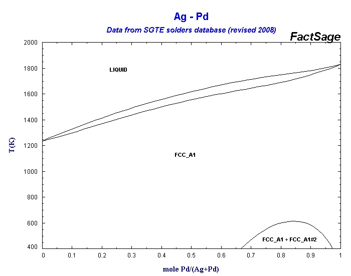
Pd Ag Phase Diagram And Cooling Curve

Phase Diagram Of Pd Ag System Download Scientific Diagram By removing the time axis from the curves and replacing it with composition, the cooling curves indicate the temperatures of the solidus and liquidus for a given composition. this allows the solidus and liquidus to be plotted to produce the phase diagram: this page titled 12.5: interpretation of cooling curves is shared under a cc by nc sa. A region of the copper zinc phase diagram that has been enlarged to show eutectoid and peritectic invariant points , labeled e (5600 c, 74 wt% zn) and p (598 0 c, 78.6 wt% zn), respectively. figure by mit ocw. note that each single phase field is separated from other single phase fields by a two phase field.

The Calculated Ag Pd Phase Diagram With Experimental Points Ref 4 5 Equilibrium phase diagrams are one of the single most useful tools of a materials scientist and engineer. as maps of the temperature ranges and solubility limits of each known phase in the alloy system, including compounds, they are obviously useful to metal casters, heat treaters and ceramicists and are an invaluable tool in alloy design, in. As the alloy cools from 1200 c to 200 c, the phases and their compositions will change according to the phase diagram of ag cu. initially, the alloy will be in the liquid phase and it will begin to solidify as it reaches the liquidus line. at this point, the composition of the alloy will be 40 wt% ag. as the temperature continues to decrease. This range is bound by the liquidus curve, above which the entire material is liquid, and the solidus curve, below which the entire material is solid. figure 1: annotated ag au binary phase diagram depicting a fully miscible with an insert magnifying the l (ag,au) two phase region. single phase regions are purple and two phase regions are white. Phase diagram and “degrees of freedom”. phase diagrams is a type of graph used to show the equilibrium conditions between the thermodynamically distinct phases; or to show what phases are present in the material system at various t, p, and compositions. “equilibrium” is important: phase diagrams are determined by using slow cooling.

Collection Of Phase Diagrams This range is bound by the liquidus curve, above which the entire material is liquid, and the solidus curve, below which the entire material is solid. figure 1: annotated ag au binary phase diagram depicting a fully miscible with an insert magnifying the l (ag,au) two phase region. single phase regions are purple and two phase regions are white. Phase diagram and “degrees of freedom”. phase diagrams is a type of graph used to show the equilibrium conditions between the thermodynamically distinct phases; or to show what phases are present in the material system at various t, p, and compositions. “equilibrium” is important: phase diagrams are determined by using slow cooling. The pd ag cu ternary phase diagram at 400°c can be seen in figure 1. each vertex of the triangle equates to a pure element and the triangle’s edges corresponds to the binary phase diagram at the given temperature. between each single phase region (white) exists a two phase region (purple) and between each two hase regions exist a three. By removing the time axis from the curves and replacing it with composition, the cooling curves indicate the temperatures of the solidus and liquidus for a given composition. this allows the solidus and liquidus to be plotted to produce the phase diagram: this page titled 4.2.5: interpretation of cooling curves is shared under a cc by nc sa.

Comments are closed.