Pilot Automotive Relay Wiring Diagram

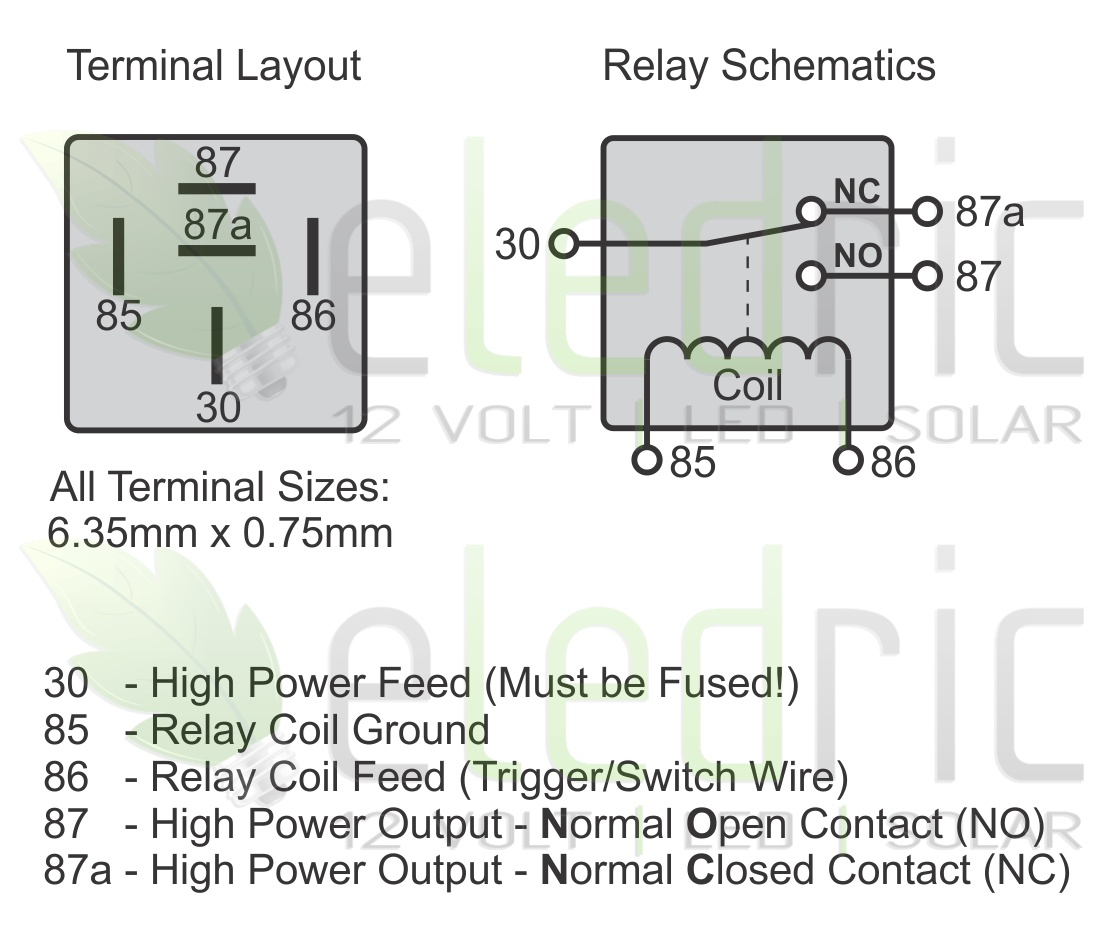
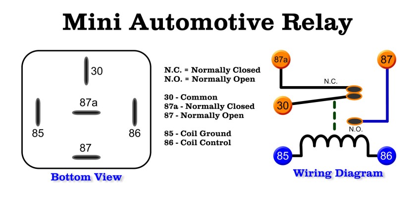
Relay Wiring Numbers Wiring Diagram And Schematics Here we will only discuss the relay’s connection points. below is the circuit diagram of the four and five pin car relays. 5 pin relay wiring diagram on relay case. according to din 72552 standard, each pin of a relay is numbered 85, 86, 30, 87, and 87a. you need to know that a relay has two circuits, a coil circuit (also called a “low. 5 pin relay diagram. both these relays are very similar except that the 4 pin relay doesn’t have the ‘87a’ or the normally closed (nc) pin whereas the 5 pin relay has it. another major classification of automotive relays is the positioning of com pin in the relay. depending on position of the com relays are further classified into: type a.

Wire A Relay Diagram When the relay is energized, the connection between pins 30 and 87a is opened, interrupting the current flow to the load. to wire a 5 pin relay, start by connecting pin 30 to the power source and pin 85 to the ground. then, connect pin 86 to the switch or control unit, and pin 87 to the load. Instructions for wiring a standard automotive relay with descriptions of the pin out and the schematic. i go over what each contact of the relay is for, and. An auto relay is an electrical device that controls the flow of electrical current in a circuit. it is commonly used in automotive applications to control various electrical systems, such as headlights, air conditioning, and starter motors. auto relays are typically composed of a coil, a set of contacts, and a switch mechanism. However, with a step by step approach, you can easily decode the diagram and understand how the relay functions. here’s a guide to help you navigate through the diagram and understand its different components. 1. identify the relay symbol: the first step is to locate the relay symbol on the wiring diagram.

Automotive Relay Wiring Diagram Keep Going And Going And Wiring An auto relay is an electrical device that controls the flow of electrical current in a circuit. it is commonly used in automotive applications to control various electrical systems, such as headlights, air conditioning, and starter motors. auto relays are typically composed of a coil, a set of contacts, and a switch mechanism. However, with a step by step approach, you can easily decode the diagram and understand how the relay functions. here’s a guide to help you navigate through the diagram and understand its different components. 1. identify the relay symbol: the first step is to locate the relay symbol on the wiring diagram. 4 pin relays have 4 pins emerging from a plastic casing: 87 – common contact for normally open or normally closed. 30 – power in for the electromagnet coil. 87a – normally closed contact. 85 – power out from electromagnet coil. inside there are spring loaded contacts connected to pins 87 and 87a. when at rest, 87a makes contact within. An automotive relay is an electrical device used in vehicles to control and switch high power circuits. it acts as a switch that allows a low power circuit to control a high power circuit, thus protecting the low power circuit from damage. how does an automotive relay work? an automotive relay typically consists of a coil, an armature, and a.

Comments are closed.