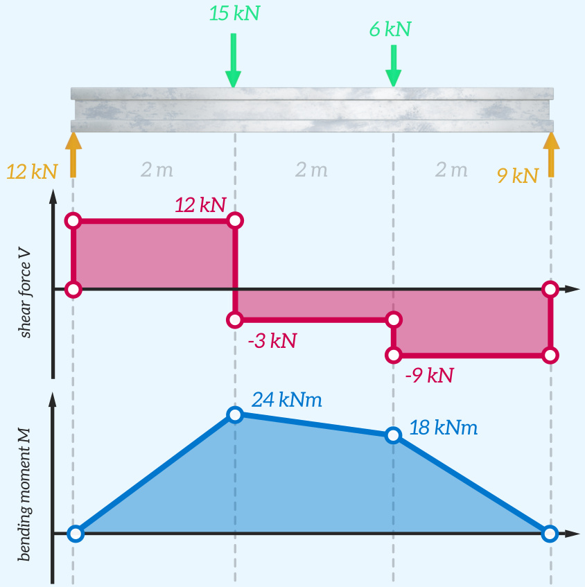
Shear Force And Bending Moment Diagram Practice Problem 3

Diagram Torque Bending Moment Diagram Mydiagram Online Check out engineer4free structural analysis for more free structural analysis tutorials. the course covers shear force and bending moment diag. The quick way to solve sfd & bmd problems. shear force and bending moment diagram practice problem #1; shear force and bending moment diagram practice problem #2; shear force and bending moment diagram practice problem #3; shear force and bending moment diagram practice problem #4; shear force and bending moment diagram practice problem #5.

How To Draw Bending Moment Diagrams Waypush7 The two expressions above give the value of the internal shear force and bending moment in the beam, between the distances of the 10 ft. and 20 ft. a useful way to visualize this information is to make shear force and bending moment diagrams which are really the graphs of the shear force and bending moment expressions over the length of the beam. Plots of v(x) and m(x) are known as shear and bending moment diagrams, and it is necessary to obtain them before the stresses can be determined. for the end loaded cantilever, the diagrams shown in figure 3 are obvious from eqns. 4.1.1 and 4.1.2. figure 4: wall reactions for the cantilevered beam. The shear and moment diagrams are both used primarily in the analysis of horizontal beams in structures, such as floor joists, ceiling joists, and other horizontal beams used in construction. figure 6.5.3 6.5. 3: the horizontal beams under this bridge surface will be supporting load forces perpendicular to the length of the beam. Select from the following links of solved examples. problem 5 3 calculate the values and draw the diagram for shear force and bending moment for a simply supported beam with overhang. problem 5 2 calculate the values and draw the diagram for shear force and bending moment for a simply supported beam subjected to point load and uniform load.

Basic Shear Bending Moment Diagrams The shear and moment diagrams are both used primarily in the analysis of horizontal beams in structures, such as floor joists, ceiling joists, and other horizontal beams used in construction. figure 6.5.3 6.5. 3: the horizontal beams under this bridge surface will be supporting load forces perpendicular to the length of the beam. Select from the following links of solved examples. problem 5 3 calculate the values and draw the diagram for shear force and bending moment for a simply supported beam with overhang. problem 5 2 calculate the values and draw the diagram for shear force and bending moment for a simply supported beam subjected to point load and uniform load. Separated by a distance or lever arm, z. z z. you might recognise this pair of forces as forming a couple or moment m m. m = f c\times z = f t\times z \tag {2} m = f c ×z =f t ×z (2) 💡 the internal bending moment m m, is the bending moment we represent in a bending moment diagram. the bending moment diagram shows how m m (and therefore. Subject strength of materialsvideo name sfd and bmd for cantilever beam problem 3chapter shear force and bending moment in beamsfaculty prof. zafar.

Comments are closed.