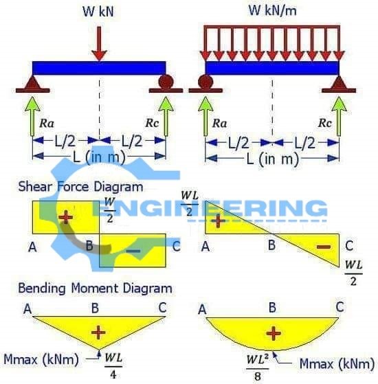
Shear Force Bending Moment Formulas With Diagram Ccal Shear Forceођ

Bending Moment And Shear Force Formula S Engineering Information Hub Introduction notations relative to “shear and moment diagrams” e = modulus of elasticity, psi i = moment of inertia, in.4 l = span length of the bending member, ft. r = span length of the bending member, in. m = maximum bending moment, in. lbs. p = total concentrated load, lbs. r = reaction load at bearing point, lbs. v = shear force, lbs. Successive integration method figure 8: relations between distributed loads and internal shear forces and bending moments. we have already noted in equation 4.1.3 that the shear curve is the negative integral of the loading curve. another way of developing this is to consider a free body balance on a small increment of length \(dx\) over which the shear and moment changes f.

Shear Force Bending Moment Diagram For Civil And Engineering Getmyuni . lecture 1 4: shear force and bending moment. of shear force and bending moment in beams:when the beam is loaded in some arbitrarily manner, the internal forces and moments are developed and the terms shear force and bending moments come into pictures wh. ch are helpful to analyze. Step 1 | draw a free body diagram. to correctly determine the shear forces and bending moments along a beam we need to know all of the loads acting on it, which includes external loads and reaction loads at supports. by drawing the free body diagram you identify all of these loads and show then on a sketch. The moment diagram will plot out the internal bending moment within a horizontal beam that is subjected to multiple forces and moments perpendicular to the length of the beam. for practical purposes, this diagram is often used in the same circumstances as the shear diagram, and generally both diagrams will be created for analysis in these. 4.3 shear forces and bending moments consider a cantilever beam with a concentrated load p applied at the end a, at the cross section mn, the shear force and bending moment are found fy = 0 v = p m = 0 m = p x sign conventions (deformation sign conventions) the shear force tends to rotate the material clockwise is defined as positive.

Comments are closed.