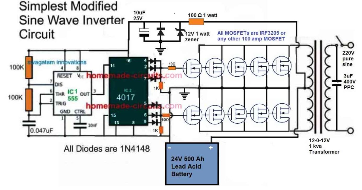
Simple Inverter Circuit Diagram 1000w

Simple Inverter Circuit Diagrams 1000w A relatively simple 1000 watt pure sine wave inverter circuit is explained here using a signal amplifier and a power transformer. as can be seen in the first diagram below, the configuration is a simple mosfet based designed for amplifying current at 60 volts such that the connected transformer corresponds to generate the required 1kva output. Based on the datasheet, a simple 2.2uf 350v (non polarized) capacitor should work. i made a simple breakout board for it, having three screw terminals connected in parallels to it. a pair of wires goes to the transformer's hv output, another pair to the outlet and another pair back to the feedback input of the main inverter board.

Simple Inverter Circuit Diagrams 1000w Thank you for watching!in this video, i will show you how to make a simple powerful 1000 watt inverter, a diy inverter 12v to 220v | pure sine wave inverter . Here we designed a simple sine wave inverter circuit that produces 50hz quasi sine wave output using a single ic cd4047 and some discrete components, which makes it a very cost effective solution. parts required: parts list sine wave inverter circuit diagram. the diy sine wave inverter circuit using ic 4047 is given below. Connect the 27 (9v) batteries in series in the below shown schematic, it will give around 245vdc: battery for transformerless inverter. solder the output ve and –ve terminals with thick wires. now connect the battery bank’s output to a 40 watt 230v tungsten bulb, it should glow at full brightness. A 1000w pure sine wave inverter is an important component of any renewable energy system, providing clean and steady electricity for a wide variety of applications. the circuit diagram for this inverter is quite straightforward, but understanding the components and how they work together to produce a power supply can seem daunting.

Simple Inverter Circuit Diagram 1000w Connect the 27 (9v) batteries in series in the below shown schematic, it will give around 245vdc: battery for transformerless inverter. solder the output ve and –ve terminals with thick wires. now connect the battery bank’s output to a 40 watt 230v tungsten bulb, it should glow at full brightness. A 1000w pure sine wave inverter is an important component of any renewable energy system, providing clean and steady electricity for a wide variety of applications. the circuit diagram for this inverter is quite straightforward, but understanding the components and how they work together to produce a power supply can seem daunting. Easy way to make a powerful 1000w inverter project. This 1000 watt power inverter circuit diagram based on mosfet rf50n06.if you want more power then add additional mosfet paralleled at rf50n06.this mosfets are 60 volts and 50 amps as rated. it is necessary to connect a fuse with the power line and always a load have to connected while power is being applied . the output power of this inverter.

Comments are closed.