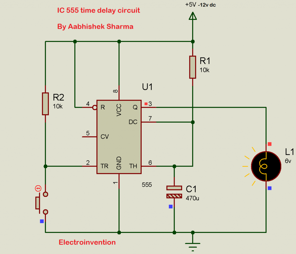
Simple Time Delay Circuit Using 555 Timer

Time Delay Circuit Using 555 Timer A time delay circuit can be useful for any circuit that needs a delay before the output turns on. in order to obtain time delay, we are using a 555 timer ic for this purpose. we can adjust the time of delay by changing the values of the resistor and capacitor used in the circuit. buy now. Before going into detail of time delay circuit, first we need to learn about 555 timer ic first. below you can find the pin diagram of 555 timer ic along with the details of each pin. pin 1. ground: this pin should be connected to ground. pin 2. trigger: trigger pin is dragged from the negative input of comparator two.

Time Delay Circuit Using 555 Timer 5 working of time delay circuit: simple time delay circuit uses 555 timer ic to create a time delay. the time delay circuit has 2 switches, one is responsible to start the time delay and the second is responsible to trigger the rest. the circuit also consists of a potentiometer to adjust the time delay. it gives the advantage to vary the time. When the pushbutton is pressed, the countdown timer starts and the green led turns on after the particular time (defined by the formula t= 1.1*r1*c1) the 555 timer goes into a stable state, where the red led turns on and the green led turns off. you can increase and decrease the time delay by using the 100k potentiometer. In this article, i have shared the required components, complete circuit diagram, pcb layout, and all other details for this simple 555 timer project. time delay relay circuit diagram. in this circuit, if you want to use the 5v dc supply, then use the 5 volt relay instead of the 12 volt relay. the delay time depends on the r2 resistor and c1. The 555 timer delay before turn on circuit we will build is shown below. the breadboard schematic of the above circuit is shown below. to connect power to the 555 timer chip, we connect about 5 15v to v cc, pin 8 and we connect pin 1 to ground. we connect a 100μf capacitor to the positive voltage supply and then to pin 2.

Comments are closed.