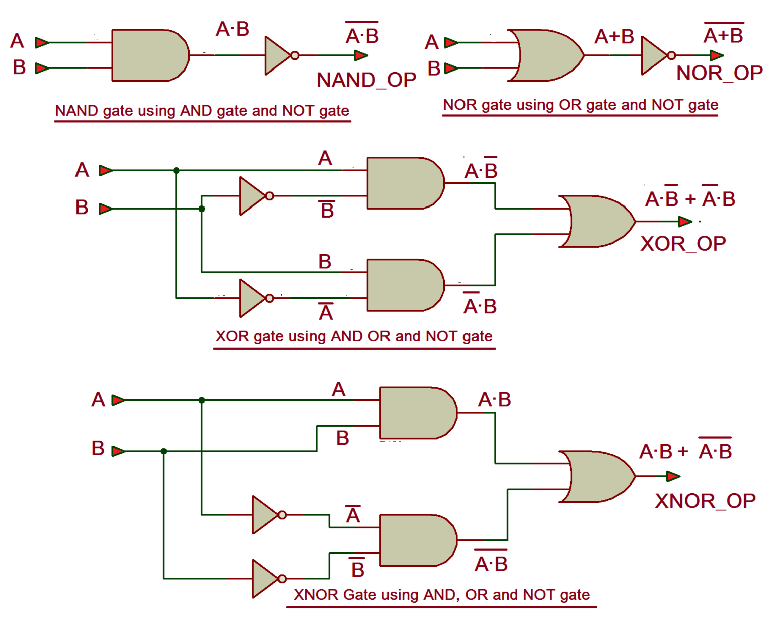
Simulation Working Of All Basic Logic Gates And Nand Or Nor Not

Simulation Working Of All Basic Logic Gates And Nand Or Nor Not Logic gate simulator. a free, simple, online logic gate simulator. investigate the behaviour of and, or, not, nand, nor and xor gates. select gates from the dropdown list and click "add node" to add more gates. drag from the hollow circles to the solid circles to make connections. right click connections to delete them. Simulation of all basic logic gates on android app:"every circuit".

Vhdl Tutorial вђ 5 Design Simulate And Verify Nand Nor Xor And Xnor Truth table for and gate. the and gate performs the operation on the basis of simply multiplication and multiplication is also known as the and function. the output of the and gate is given by. y= a.b. where dot ‘.’ represent the and logic. here, a and b denotes the inputs. the output is given by y. the total number of possible. Before scripting the vhdl program, first, we need to create a project in the modelsim. the steps to create the project are given below. step 1: open modelsim. step 2: click file >new >project. step 3: the create new project dialog box opens up. enter the name for your project and click ok as shown below. As in each of the first three cases, a full and (which would be true and true) isn't present. hence, the outcome is true (1). for the last input, true and true, a full and is present and thus (due to the not component, the n in nand), the outcome is false. in this image, we see an sn7400n chip that has four logic gates, namely, nand gates. Dive into the world of logic circuits for free! from simple gates to complex sequential circuits, plot timing diagrams, automatic circuit generation, explore standard ics, and much more. launch simulator learn logic design.

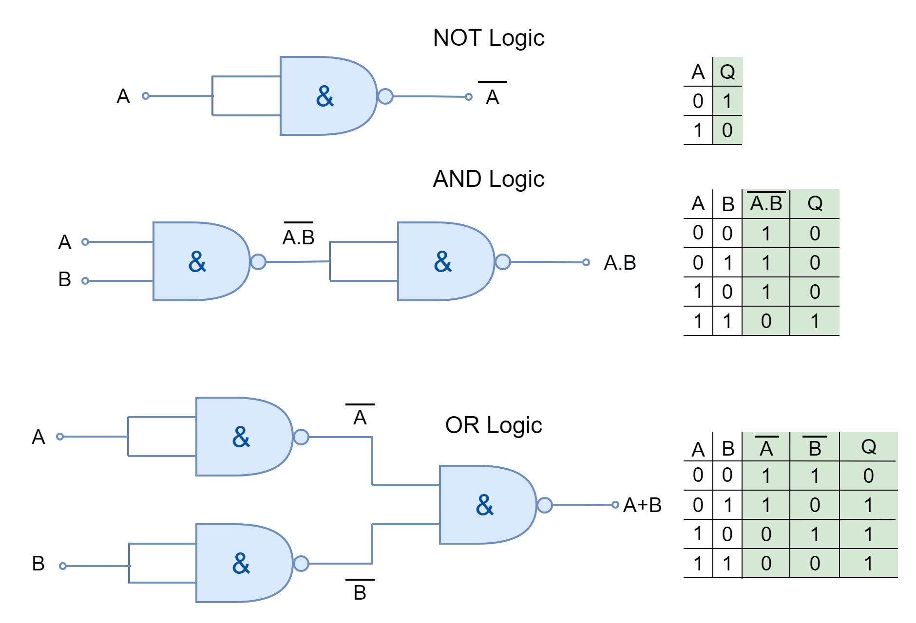
Logic Gates Using Nor Gate As in each of the first three cases, a full and (which would be true and true) isn't present. hence, the outcome is true (1). for the last input, true and true, a full and is present and thus (due to the not component, the n in nand), the outcome is false. in this image, we see an sn7400n chip that has four logic gates, namely, nand gates. Dive into the world of logic circuits for free! from simple gates to complex sequential circuits, plot timing diagrams, automatic circuit generation, explore standard ics, and much more. launch simulator learn logic design. This video covers all basic logic gates and how they work. in this video i have explained and, or, not, nor, nand, xor and xnor gate along with their truth t. A universal gate is a logic gate that can be used to implement other types of logic gates. in other words, using a universal gate, you can do all the simple operations like and, or, not, nand, and nor. the two most general purpose nand gates and nor gates. these gates are considered universal because they can be used to create all other logic gates.

Logic Gate Simulation On Proteus Not Or And Nand Nor Xor Gate This video covers all basic logic gates and how they work. in this video i have explained and, or, not, nor, nand, xor and xnor gate along with their truth t. A universal gate is a logic gate that can be used to implement other types of logic gates. in other words, using a universal gate, you can do all the simple operations like and, or, not, nand, and nor. the two most general purpose nand gates and nor gates. these gates are considered universal because they can be used to create all other logic gates.

Comments are closed.