Single Phase Motor Wiring Single Phase Motor Connection With Switch House Wiring

Single Phase Motor Wiring Single Phase Motor Connection Single phase motor wiring | single phase motor connection with switch | house wiring | complete house wiring with inverter connection | single phase full hou. By the end of this guide, you will have a thorough understanding of single phase motor wiring connection and will be able to confidently wire these motors in various applications. section 1: understanding single phase motors. a single phase motor is a device that converts electrical energy into mechanical energy, consisting of a stator and a rotor.

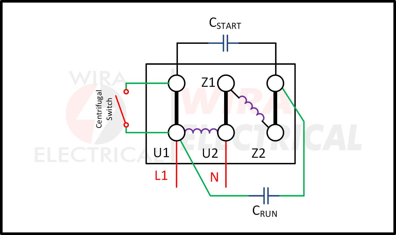
Electric Motor Single Phase Wiring Diagram Permanent split phase capacitor motor wiring diagram. just as its name implies, this single phase motor diagram will work with a split phase generated by a capacitor. the capacitance from the capacitor and the reactance from the winding will shift the phase to some extent. below is the permanent capacitor single phase motor wiring diagram. The motor wiring diagram provides a visual representation of the electrical connections for a single phase motor. it illustrates how the different components, such as the power supply, start capacitor, run capacitor, centrifugal switch, and winding connections, are connected to each other. typically, single phase motors have two types of. The wiring diagram for a 120 volt single phase motor will typically show the connections for the power supply, start winding, run winding, and any additional components such as a capacitor. the power supply will usually have two wires – a line wire and a neutral wire. the line wire is typically black and the neutral wire is typically white. Strip the wires. using the wire strippers, carefully strip the ends of the motor wires to expose the bare copper. make sure to strip off enough insulation to make a secure connection. 4. connect the power wires. identify the power wires in the diagram and connect them to the appropriate terminals on the motor.

Single Phase Motor Wiring Diagram And Examples Wira Electrical The wiring diagram for a 120 volt single phase motor will typically show the connections for the power supply, start winding, run winding, and any additional components such as a capacitor. the power supply will usually have two wires – a line wire and a neutral wire. the line wire is typically black and the neutral wire is typically white. Strip the wires. using the wire strippers, carefully strip the ends of the motor wires to expose the bare copper. make sure to strip off enough insulation to make a secure connection. 4. connect the power wires. identify the power wires in the diagram and connect them to the appropriate terminals on the motor. Common problems and troubleshooting single phase motor wiring. 1. motor not starting or not running smoothly. if the single phase motor is not starting or running smoothly, the problem may lie in the wiring. check the connection points for any loose or damaged wires, and ensure that all connections are properly tightened. In order to properly wire a single phase motor, it is important to understand the wiring diagram and the connections required. the wiring diagram will provide the necessary information about the motor’s terminals, the starting and running capacitors (if applicable), and the direction of rotation. it is crucial to follow the wiring diagram and.

Comments are closed.