The Continuous Cooling Transformation Diagram For 76

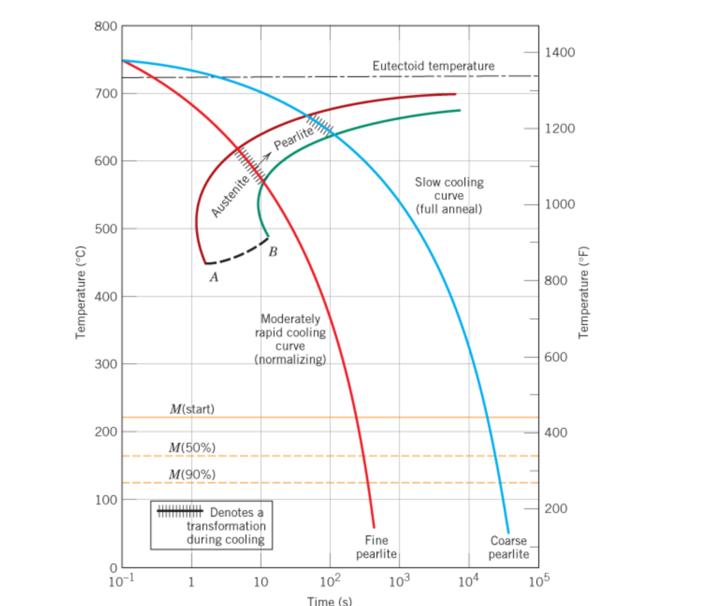
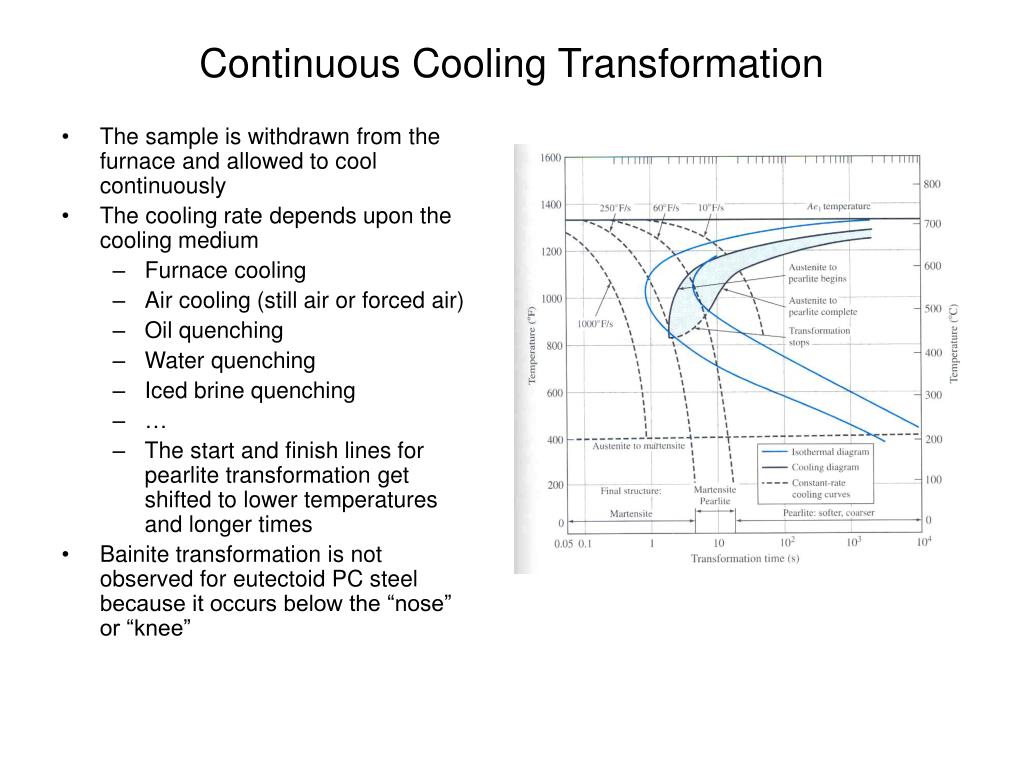
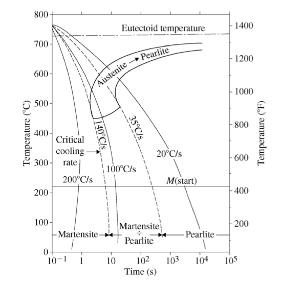
Continuous Cooling Transformation Diagram Definition: stability of phases during continuous cooling of austenite. there are two types of cct diagrams. i) plot of (for each type of transformation) transformation start, specific fraction of transformation and transformation finish temperature against transformation time on each cooling curve. There are two types of continuous cooling diagrams drawn for practical purposes. type 1: this is the plot beginning with the transformation start point, cooling with a specific transformation fraction and ending with a transformation finish temperature for all products against transformation time for each cooling curve. type 2: this is the plot.

Continuous Cooling Transformation Diagram Fig. 3.14 illustrates a derived cct diagram for eutectoid steel and its relationship to ttt curve. generally, continuous cooling shifts the beginning of the austenite transformation to lower temperatures and for longer times. this is explained as cooling curve ‘c’ (fig. 3.14) intersects at (a) the beginning of the pearlite transformation. 1. introduction. to evaluate the performance of structural steels, understanding its microstructure after processing is crucial. the continuous cooling transformation (cct) diagram of a steel plays an important role in providing information on the steel microstructure, as the information includes the start temperatures of phase transformation during cooling, as well as hardness. Figure 10.40 shows the continuous cooling transformation diagram for a 0.35 wt\% $\mathrm{c}$ iron carbon alloy. make a copy of this figure and then sketch and label continuous cooling curves to yield the following microstructures: (a) fine pearlite and proeutectoid ferrite (b) martensite (c) martensite and proeutectoid ferrite. Figure $10.40$ shows the continuous cooling transformation diagram for a $1.13 \mathrm{wt} \%$ c iron carbon alloy. make a copy of this figure and then sketch and label continuous cooling curves to yield the following microstructures: (a) fine pearlite and proeutectoid cementite (b) martensite (c) martensite and proeutectoid cementite.

Ppt Chapter 10 Powerpoint Presentation Free Download Id 5893032 Figure 10.40 shows the continuous cooling transformation diagram for a 0.35 wt\% $\mathrm{c}$ iron carbon alloy. make a copy of this figure and then sketch and label continuous cooling curves to yield the following microstructures: (a) fine pearlite and proeutectoid ferrite (b) martensite (c) martensite and proeutectoid ferrite. Figure $10.40$ shows the continuous cooling transformation diagram for a $1.13 \mathrm{wt} \%$ c iron carbon alloy. make a copy of this figure and then sketch and label continuous cooling curves to yield the following microstructures: (a) fine pearlite and proeutectoid cementite (b) martensite (c) martensite and proeutectoid cementite. In the present work, continuous cooling transformation (cct) of coarse grained heat affected zone (cghaz) and simulation of charpy sized impact specimens were performed using a gleeble 3800 thermomechanical simulator. results obtained from the dilation studies show significant effect of cooling rates on microstructure and low temperature (–20 °c) charpy impact toughness. phase. Continuous cooling transformation (cct) diagrams are the most frequent and widely used tool to design specific heat treatments and predict the resulting microstructures and mechanical properties of a specific steel [4]. unfortunately, most cct diagrams in steels have been constructed from temperatures where austenite is the stable phase (full.

Continuous Cooling Transformation Diagram Download Scientific Diagram In the present work, continuous cooling transformation (cct) of coarse grained heat affected zone (cghaz) and simulation of charpy sized impact specimens were performed using a gleeble 3800 thermomechanical simulator. results obtained from the dilation studies show significant effect of cooling rates on microstructure and low temperature (–20 °c) charpy impact toughness. phase. Continuous cooling transformation (cct) diagrams are the most frequent and widely used tool to design specific heat treatments and predict the resulting microstructures and mechanical properties of a specific steel [4]. unfortunately, most cct diagrams in steels have been constructed from temperatures where austenite is the stable phase (full.

Continuous Cooling Transformation Cct Diagram Of As Cast Dp Steel

Comments are closed.